Location and Design Division
MicroStation / OpenRoads Standards 2016
This section is intended to provide information on VDOT’s OpenRoads Standards. Each section below provides information on how the Department utilizes the software or changes that have been made to legacy versions of MicroStation.
Implementation of OpenRoads Technology on Roadway Projects
The finalized implementation schedule for projects designated to use OpenRoads Technology is outlined below and was developed with the assistance of District and Central Office staff.
In accordance with the State Location & Design Engineer’s email sent on May 20th 2016, the following applies to Roadway Projects.
- Open Roads technology will be used by VDOT staff and consultant design firms on all minimum plan projects and above where new survey was completed on or after January 1, 2016.
- As an option, Open Roads technology can be used on other projects that were surveyed before January 2016 if these projects have not entered the Public Involvement phase
VDOT uses Bentley Products MicroStation and GEOPAK for Drafting, Survey and Road Design Work. Bentley is integrating MXroad, GEOPAK, and Inroads into one product line. Bentley is now calling the latest releases Open Roads Technology.
VDOT’s Current versions
- Bentley MicroStation V8i (SELECTseries 4) Version 08.11.09.832
- Bentley GEOPAK Suite (SELECTseries 4) Version 08.11.09.872
VDOT’s Work Space
msv8i_update_SS4_2015_CON.EXE (consultant version)
or
msv8i_update_SS4_2015.EXE (In house version) Installs all the VDOT configuration and resource files including a desktop icon to run the VDOT configuration.
VDOT utilizes a redirect file (LUVDOT_Stnds_Local.cfg) to force MicroStation and GEOPAK to use VDOT’s variables and resources. This file is installed in C:\Program Files (x86)\Bentley\MicroStation V8i (SELECTseries)\MicroStation\config\appl
*Note – If MicroStation has been installed in a different location then this file will need to be moved to the correct location.
*Note – If desired this LUVDOT_Stnds_Local.cfg file extension can be renamed or removed so that MicroStation and GEOPAK will run the default Bentley setup.
The VDOT configurations and resources are installed by default to the local
c:\proj\supv8i2015 folder. In the redirect file we could change this location to a server or another drive if needed or desired.
*Note – If you are using a server or different drive the supv8i2015 folder will
need to be moved to the correct location.
The supv8i2015 folder will contain the following items:
- cfg, ucf, and pcf files for variables and plotting.
- dgnlib files for the gui, levels, element templates, features, civil cells, and settings
- normal cells, line styles, fonts, vba, macro and seed files, color tables, pen tables, GEOPAK ddb files, template library, label library, and standards files.
Consultant Installation Process
The current software is available for download on the VDOT FTP Server and is located in the download/V8i(SS4)Open_Roads-CADD-Package-Software-Download. There is a readme.txt file in this folder with installation instructions. Please follow the instructions to get the software and resource install correctly.
Readme.txt
Please download all the directories and files.
Please uninstall old versions.
Please TURN OFF UAC and Reboot before installing.
Please Load in the order listed.
Please use all the default settings.
Please use the VDOT desktop icon to start MicroStation.
MicroStation
1. \MicroStation V8i (SELECTseries 4) 08.11.09.832\setup.exe ==> Installs MicroStation Version 08.11.09.832
GEOPAK
2. \GEOPAK_Suite_SS4_08_11_09_878\setup.exe ==> Installs GEOPAK Version 08.11.09.878
MicroStation Update
3. \msv8i_update_SS4_2015_CON.EXE ==> Installs all the VDOT configuration and resource files for v8i including a desktop icon to run the VDOT configuration.
Consultant Updates
All updates for the variables and resources will be included in the msv8i_update_SS4_2015_CON.EXE and updated as significant changes occur to the variables and resources.
*Note – Consultants need to check this file periodically for updates. The EXE will overwrite only the updated files on the local c:\proj\supv8i2015 folder.
*Note – If the user has modified one of the resource files and the date was older than the one in the EXE it will be overwritten but if it has a newer date it will not be overwritten.
*Note – If Consultants do not have access to the VDOT FTP Server and need our resource files immediately please Click Here to download the form for Large File Transfer Request. Email the completed form to the CADD Support Helpdesk. We have a Transfer Utility that will allow us to send the file if immediately needed.
*Note – If Consultants do not have access to the VDOT FTP Server MicroStation Version 08.11.09.832 and GEOPAK Version 08.11.09.878 software can also be downloaded from the Bentley Website if they have access there.
VDOT is transitioning from Feet to US Survey Feet
Starting in 2014, VDOT is migrating to the Open Roads platform. During this migration, VDOT is also transitioning from the legacy International Foot working units (Feet) seed file to the US Survey Foot working units (US Survey Feet) seed file per Section § 55-290 of the Code of Virginia for new projects.
US Survey Foot Seed Files - (US Survey Feet)
- New 2D and 3D seed files are provided that are set to the US Survey feet working unit (US Survey Feet) and should be used for Projects that the Survey files are set to US Survey Feet.
- New Seed files are located in the following directory:
US Survey Foot
(SS3 / SS4 / ss10) - proj\supv8i2015\seed\US Survey Foot
The seed files are also available in Falcon for internal uses
Named: USFootSeed.dgn (2D file) & USFootSeed3D.dgn (3D file)
_________________________________________________________________
Legacy International Foot Seed Files - (Feet)
- Legacy files are dgn files started prior to July 2014 that uses the legacy Imperial foot (Feet) as a working unit.
- Any drawings created in association with legacy project files MUST use the legacy seed file which is set to the International foot (Feet).
- Seed files for legacy project files are located in:
(SS2) - proj\supv8i\seed
(SS3 / SS4 / ss10) - proj\supv8i2015\seed\Imperial
The seed files are also available in Falcon for internal uses
_________________________________________________________________
The following are the differences between the two:
- 1 US Survey Foot = 1.000002 International Foot
- This is a difference of 2 ten-thousandths in 100 feet. It is generally not significant when measuring distances within our projects. However, the origin of our coordinate system is far enough away that you will have a significant error if you try to superimpose (reference) graphics drawn in one system over graphics drawn in the other.
_________________________________________________________________
Key Points to Remember:
In 2014, Survey started providing projects in the US Survey foot seed file for new projects. New projects may use the international seed file if the new project is tying into an old legacy project. This should be determined prior to commencing survey.
All VDOT and consultant staff are responsible for verifying and using the proper seed file when work is assigned.
NEVER MIX WORKING UNITS.
Named Level Structure
Separate named levels have been provided for text, line styles, and cell symbology per feature.
All levels are preset with color, weight, and line style based on chapters and appendices in the Cadd manual. Color overrides are still available.
Levels can be segregated by plan, utility, DTM, and existing boundary with the following display filters. These filters can be used to create the individual files.
Example:
Survey. PLAN FEATURES -displays plan feature without points
Survey. EXISTING FEATURES –displays boundary features without points
Survey. DTM FEATURES -displays DTM features
Survey. UTIL FEATURES -displays utility features without points.
Level Structures
Updated Cell Names & Libraries
• All legacy cells are available in the survey cell library.
• Updated cells are based on the old legacy cells and have been set to annotative in the survey14 cell library.
• Photogrammetry has new cells based on their level structure in SurveyPhoto cell library.
• Note: New cells are annotative in nature and if placed manually they should be at 1 scale.
If the scale is changed the cell will adjust accordingly. At a 25 scale (12x25=300) cells will ID at 300.
New Cell Libraries
Collection of Civil Elements
A civil cell is a collection of civil elements - geometry, templates, and terrain models - which can be placed repeatedly in a design. The collection of civil elements will have been created relative to one or more reference elements. When you place the civil cell, you choose the new reference elements, and a new collection of civil elements is then created relative to them. A civil cell can therefore be thought of as a copy of the original collection of civil elements, relative to the geometry of the new reference elements. Civil cells can be 2D or 3D. They can consist of 2D (plan) elements only, or 3D elements (2D elements with profiles), and can include terrains, linear templates, area templates, and simple corridors.
When the new civil elements are created, all of the rules associated to them are also created. This means that the new civil elements retain their relationships, both with each other and with the reference elements, and therefore know how to react when these relationships change. In addition, the Civil and MicroStation toolsets can still be used on the new civil elements, to adjust and further refine the design as required, because there is no difference between a civil element created by a civil tool, and one created by placing a civil cell.
Civil cells can save a lot of time and effort, because they replicate the complete series of steps needed to create the civil elements. They also help to ensure compliance with design standards, by making a civil cell available to the design team.
- VDOT Intersection Civil Cells
Annotative Elements – Text & Cells
Line styles, text & cells are annotative. Some cells are annotative but not all. Cells that have set values do not scale up or down these cells are meant to represent true values as they would be built or measured. Cells that are used for labeling or to show objects location are annotative. Most of the Survey cells are annotative as they usually represent where an object is located.
If you are referencing a survey file to legacy file that is 1 to 1, you will need to turn off the annotative option on the reference file. Text and cells will be really small if this is not correct. Set Global Line Style Scale to Reference

Annotative Scale
Line styles, text & cells are annotative. Some cells are annotative but not all. Cells that have set values do not scale up or down these cells are meant to represent true values as they would be built or measured. Cells that are used for labeling or to show objects location are annotative. Most of the Survey cells are annotative as they usually represent where an object is located.
Annotative Text
Survey specific text styles have been setup (Font 23 (Italics).
| Survey_Contours | for use in displaying contour text | set to 0.01 |
| Survey_Owner _Text | for use in adding owner’s names | set to 0.0133 |
| Survey-Owner_DBPG_Text | for use in owner db, pg, tax, etc., information | set to 0.01 |
| Survey_Text | for use with general text | set to 0.01 |
This text is annotative as well and will ID as the heights listed above. Text will change size based on the scale of the file. (25 scale> .01 x 12 x 25=3)
Global Line Style Scale
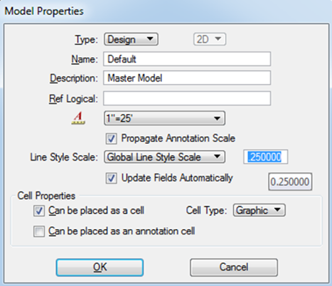
Line style scales have NOT changed and must be set manually when changing scales. It can be set in each model from File – Models right click on the default model and select properties.
Change Global Line Style Scale to the appropriate scale
0.25 - 25 Scale
0.50 - 50 Scale
1.00 - 100 Scale
New seed files are preset to 0.25.


Dynamic Typical Sections
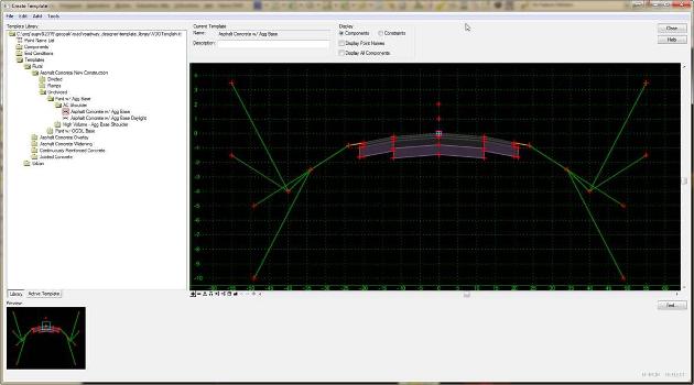
Templates are dynamic typical sections used in Corridor Modeling that use transverse geometry to create 3D models. Each template contains a series of points and components that represent breaklines, which are used to create the roadway surfaces. All these points, components, and templates are stored in the template library (itl). CADD Support has created a default template library. This library contains most used components and end conditions at VDOT. A limited number of templates are available through this template library. Enough variables have been added to cover most conditions along with the use of point control. The intent is for the user to use this template library unless conditions arise that modifications are necessary. If so, the default VDOT template library (itl) needs to be copied to the user’s working directory for modifications or creation of new templates utilizing VDOT’s components. If this occurs, we recommend naming the file UPC#.itl

VDOT MicroStation Open Roads Template Components Template Abbreviations
| Type of Asphalt, Concrete, or Materials: | |
| CTAB | Cement Treated Aggregate Base |
| OGDL | Open-Graded Drainage Layer (Open Graded Materials) |
| CRC | Continuously Reinforced Concrete |
| JPCP | Jointed Plain Concrete Pavement |
| CTA | Cement Treated Aggregate |
| CTAB | Cement Treated Aggregate Base |
| ACBC | Asphalt Concrete Base Course |
| ACIC | Asphalt Concrete Intermediate Course |
| ACSC | Asphalt Concrete Surface Course |
| ABC | Aggregate Base Course |
| Library Abbreviations: | |
| _CL | Centerline |
| _T_ | Top |
| _B_ | Bottom |
| _EP | Edge of Pavement |
| EC | Edge of Concrete |
| EXPVT | Existing Pavement |
| _R | Right |
| _L | Left |
| _RP | Right Portion (Divided Highways) |
| _LP | Left Portion (Divided Highways) |
| MED_BAR | Median Barrier |
| MED_ | Median Barrier |
| _REC_ | Recoverable |
| _SLP_ | Slope |
| _SHDR_ | Shoulder |
| DNC | Do Not Construct |
| RW | Retaining Wall |
| SW | Sidewalk |
| _EO_ | Edge Overlay |
| ACMIL_EM | Asphalt Concrete Milling-Existing Milling |
| _EXT | Extension |
| CLTS | Cement Lime Treated Soil |
| _I | Inner/inside |
| _O | Outer/outside |
| G | Graded |
| DIT_BOT | Ditch Bottom |
| EXT_L | Exterior Lane |
| _OS_ | Outside Shoulder |
| _IS_ | Inside Shoulder |
Automated Machine Guidance in Construction
3D Design and modeling is intended to facilitate Automated Machine Guidance (AMG) in construction. Bentley’s OpenRoads provides 3D Design tools and is the Department’s gateway to provide the necessary data for AMG. AMG technology can reduce time and cost of construction because of greater productivity by equipment operators,
fewer grade checks are needed, greener construction (less fuel and equipment wear), greater safety, less rework, and less survey staking required. Contractors invest in AMG for safety, productivity, and to stay competitive.
The benefits of 3D Design and AMG are well documented on the Federal Highway Administration web pages here: http://www.fhwa.dot.gov/construction/3d/
Some goals in providing the Engineering and CADD data to the contractor are to encourage the use of Automated Machine Guidance in Construction and to facilitate more accurate bidding.
What is a “Feature"?
At its simplest, a Feature is anything in your design that represents a real-world entity.
- Curb and Gutter
- Asphalt Pavement
- Manhole
- Wall
- Aggregate Base
- R/W Marker
- Ditch
- Fill Slope
- Etc.

What is a “Feature Definition”?
- Properties used to define how a feature is to be displayed, annotated, computed, etc.
- These are normally customized by each organization.
- These are normally created in advance and propagated across an organization in order to standardize designs.
Types of "Feature Definitions"
There are 3 types of feature definitions that are supported.
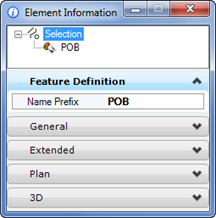
Point Feature
- R/W Marker
- Control Point
- Iron Pin
Linear Feature
- Curb & Gutter
- Wall
- Ditch
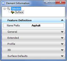
Surface Feature
- Existing Ground
- Aggregate Base
- Asphalt Pavement
Depending on its type, a feature definition will have various properties that are available for definition.
| Point | Linear |
 |
 |
| Surface | |
 |
|
Feature definitions reside in DGN Files/Libraries.
DGN Libraries (optimal)
- Allows for propagation of standards across an organization
DGN Files
- Can be created directly in DGN file, but this is not the recommended procedure
- Note: When a feature definition is used from a DGN Library, the feature definition will be copied into the DGN file. This is standard MicroStation functionality (e.g. levels, line_styles, fonts, etc.
- VDOT has several DGN Libraries with features in them. As VDOT develops the process for other areas more could be added.
Current Library List:
- Feature_Definitions_Survey.dgnlib
- Levels_element-templates_features.dgnlib
- Virginia DOT Drainage Features.dgnlib
- Virginia DOT Misc Utility FeatureDefs.dgnlib
- Virginia DOT Utility FeatureDefs.dgnlib.
This section is currently being Developed
This section is currently being Developed
This section is currently being Developed
This section is currently being Developed
This section is currently being Developed


