


Bicycle and Pedestrian Treatments
The Virginia Department of Transportation is committed to improving safety and mobility for all road users in Virginia. Safe and comfortable street design for people walking and bicycling is one of the strategies VDOT is using to achieve these goals.
Access to bicycle and pedestrian facilities is an important component of an efficient, multimodal transportation network. Providing safe and comfortable places to bike and walk enhances the quality of life and public health, strengthens communities, increases safety for all road users, reduces congestion, and benefits the environment.
There are a variety of design treatments that can improve safety and comfort for bicyclists and pedestrians. While some treatments, such as bicycle lanes, are becoming more commonplace, others may be more unfamiliar to Virginians.
This page provides information on several bicycle and pedestrian treatments. Each section includes information on the appropriate context, proper use, benefits, and design features of the given treatment(s). Examples of treatment use in Virginia and a one-page downloadable brochure are also provided.
During the planning, design, and construction phases of projects, VDOT works with local jurisdictions to incorporate these treatments into plans to facilitate the growth of a larger network of comfortable bicycle and pedestrian accommodations. While this page provides an important overview and can serve as an educational resource, local jurisdictions wishing to implement any of these treatments should consult the appropriate controlling documents, including, but not limited to, the Manual on Uniform Traffic Control Devices (MUTCD), VDOT Road Design Manual, VDOT Road and Bridge Standards, and the Code of Virginia.
Applications of treatments currently under Interim Approvals (IA) issued by the FHWA on VDOT right-of-way must be coordinated with VDOT. The FHWA Bicycle and Pedestrian Program maintains a table listing various bicycle-related signs, markings, signals, and other treatments and identifies their status (e.g., can be implemented, currently experimental) in the 2009 version of the MUTCD. Localities wishing to install these treatments should consult VDOT's list of Interim Approvals which defines the applicability of IAs already granted to VDOT. The MUTCD also maintains a list of approved requests for Interim Approval, which lists IAs by requestor; search for "Virginia" to see all the Virginia localities which have approvals.
Pedestrian Crossing Treatments
Description
Resource Links 
- High-visibility crosswalks are distinctive from standard transverse (parallel) lines in that they consist of wide longitudinal lines, a bar-pair pattern, ladder, or zebra markings.
- High-visibility crosswalks are often installed in conjunction with improved lighting and pedestrian signage.
 Aerial view of a high-visibility crosswalk (for illustrative purposes only)
How To Use a High-Visibility Crosswalk
- High-visibility crosswalks help make crosswalks and/or pedestrians more visible to motorists.
- High-visibility crosswalks can help pedestrians decide where to cross.
Context
- High-visibility crosswalks can help the driver better detect the presence of the crosswalk and potential for pedestrian crossings, particularly where a standard crosswalk might not get noticed due to roadway geometry or visual clutter.
- High-visibility crosswalks are often installed at:
- High-volume pedestrian crossings,
- Crossings ¼ mile between busy residential areas and schools or recreational areas,
- Within ¼ mile of major transit transfer locations, and
- Crossings in downtown Central Business Districts and at shared use path crossings.
Benefits
- Improved visibility: High-visibility crosswalks improve visibility of the crosswalk, increasing driver recognition distance by twice that of standard parallel lines, which equates to eight seconds of additional driving time at 30 miles per hour (mph).
- Improved safety: High-visibility crosswalks can reduce crashes by 23-48%.
Policy and Design Guidance
Guidelines are provided for informational purposes only. For detailed design guidance, please refer directly to design manuals and standards listed below in Resources.
- Either longitudinal lines (“continental”), bar pair, zebra, or ladder patterns may be used however, on VDOT-maintained roads VDOT policy is to only use continental or bar pair patterns as there is not enough evidence that zebra or ladder patterns provide any additional benefit.
- VDOT policy requires that high-visibility markings be used at:
- Multilane roundabout crossings. They should be considered at single-lane roundabout approaches and exits.
- Uncontrolled crossings of four or more lanes with speed limits greater than 35 miles mph.
- Uncontrolled crossings of three or fewer lanes where the traffic volumes exceed 15,000 vehicles per day or where the speed limit is 45 mph or greater.
- Crossings of shared use paths crossing an uncontrolled road with a speed limit greater than 25 mph.
- Pedestrian Hybrid Beacon (PHB) crossings.
- High-visibility crosswalks should also be considered at uncontrolled crossings with speed limits greater than 35 mph and where speed limits are less than 35 mph but have traffic volumes exceeding 15,000 vehicles per day.
- High-visibility crosswalks should be installed at an angle with adequate spacing to increase the longevity of the crossing.
- High-visibility crosswalks typically cost five times more than transverse parallel lines or about $8 per linear foot. The bar pairs pattern can reduce costs since they use less material while performing similarly to longitudinal line in driver recognition.

Pedestrian Crossing Accommodations at Unsignalized Locations (VDOT TE-384)
Examples of High-Visibility Crosswalks
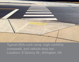
A typical ADA curb ramp, high-visibility crosswalk, and vehicle stop bar located on South Quincy Street in Arlington, Virginia.

Second example of a High Visibility Crosswalk

Bar-pair crosswalk (PedBike Images)

A fourth example of a High Visibility Crosswalk
Resources
Treatment applications and general design guidance:
- MUTCD Chapter 3B. Pavement and Curb Markings
- VDOT IIM-TE-384: Pedestrian Crossing Accommodations at Unsignalized Locations
- Virginia Supplement to the MUTCD
General guidance:
Description
Resource Links 
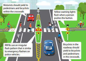
- A Rectangular Rapid Flashing Beacon (RRFB) is a pedestrian-activated device that emits rapidly flashing yellow LED lights.
- The LED lights flash long enough to allow pedestrians to cross the street in the crosswalk.
- RRFBs supplement warning signs at mid-block crossings and are a lower-cost alternative to traffic signals and pedestrian hybrid beacons (PHBs).
- Flashing beacons can also be installed overhead or in advance of an intersection. RRFBs are a unique type of beacon because of the distinct flashing pattern and signage installed under the signal.

Rendering of an RRFB (for illustrative purposes only)
How To Use an RRFB
- The RRFB is not illuminated until a pedestrian activates it via a pushbutton or by entering an automatic detection zone.
- Once activated, the yellow warning lights begin flashing, signaling to drivers that a pedestrian is ready to cross or is crossing in the crosswalk.
- Before a pedestrian enters the crosswalk, the pedestrian should make eye contact with the driver(s) to confirm they are slowing or stopping. Pedestrians should continue to scan both directions of the roadway while crossing, especially when crossing streets with multiple lanes in any direction.
- Drivers must yield to pedestrians in the crosswalk. Drivers should not pass another vehicle that has stopped at a crosswalk and should not block the crosswalk.
- Once all pedestrians have cleared the crosswalk, drivers can proceed.
- A bicyclist desiring to cross using a pedestrian warning beacon should dismount and walk their bike in the crosswalk.
Context
- The RRFB is installed in combination with pedestrian, school, or trail crossing warning signs. They cannot be installed in conjunction with other signs.
- RRFBs are installed at both ends of a crosswalk or overhead. If a crosswalk contains a pedestrian refuge island, an RRFB should be placed to the right of the crosswalk and on the median.
- RRFBs may draw power from solar panel units or be wired to a traditional power source.
- RRFBs may be installed at midblock locations or at intersections for crossings of the uncontrolled traffic movements.
- Often used with
- Crosswalk visibility enhancements
- Pedestrian refuge islands
- Advance Pedestrian Crossing warning signs and/or STOP HERE signs and markings
Benefits
- Reduced crash risk: RRFBs can reduce pedestrian crashes by 47%.
- Visibility: RRFBs can make crosswalks and pedestrians more visible at a marked crosswalk.
- Motorist yielding: RRFBs are often considered in areas with concerns for motorist yielding for pedestrians.
- Cost effectiveness: The RRFB is often less expensive than a full traffic signal or pedestrian hybrid beacon (PHB) installation.
Policy and Design Guidance
Guidelines are provided for informational purposes only. For detailed design guidance, please refer directly to design manuals and standards listed below in Resources.
- The RRFB should meet the application guidelines provided in the VDOT Traffic Engineering Division Memorandum IIM-TE-384 Attachment A, “Unsignalized Marked Crosswalk Standards.”
- RRFBs are a candidate treatment for roads with two or more lanes that generally have annual average daily traffic (AADT) above 1,500.
- RRFBs may be considered as an additional crossing treatment to supplement marked crosswalks on roadways where the speed limits are less than or equal to 45 miles per hour.
- RRFBs are not currently included in the 2009 MUTCD and may be installed in Virginia per FHWA’s Interim Approval. Localities may install RRFBs without seeking separate Interim Approval, however each road agency is responsible for ensuring they comply with FHWA’s Interim Approval requirements.
- RRFB costs range from $4,500 to $52,000 depending on power service and/or other geometric improvements (e.g., median refuge island, ramps, etc.). On average, RRFBs cost $22,250.
How to use a RRFB (AlertTodayFlorida.com)
Examples of RRFBs

RRFB installed in Fairfax County Virginia in 2019. This RRFB was installed as part of a grant through VDOT’s Pedestrian Safety Action Plan funded by FHWA's Highway Safety Improvement Program. ( Fairfax County)

RRFB installed in the City of Roanoke, Virginia. The City of Roanoke is making the City more walkable by installing RRFBs in two locations. (City of Roanoke)

RRFB installed in Arlington County, Virginia. After a systemic countywide study, the County installed RRFBs in locations to draw attention to drivers where most necessary. (Walk Arlington)
Resources
Treatment applications and general design guidance:
- VDOT IIM-TE-384: Pedestrian Crossing Accommodations at Unsignalized Locations
- FHWA STEP RRFB Fact Sheet
- FHWA Interim Approval 21 - VDOT has received IA from FHWA
- FHWA MUTCD Interpretation Letter 4-376(I)
General guidance:
- Evaluation of Rectangular Rapid Flashing Beacon System at the Belmont Ridge Road and W&OD Trail Mid-Block Crosswalk
- VDOT Pedestrian Safety Action Plan
- Fairfax County RRFBs
- City of Roanoke RRFB PSA
- City of Roanoke RRFBs
- PEDSAFE RRFB
- NCHRP 841 Development of Crash Modification Factors for Uncontrolled Pedestrian Crossing Treatments
Description
Resource Links
- Pedestrian Hybrid Beacons (PHBs) are a traffic control device that warn and control traffic at unsignalized locations.
- PHBs assist pedestrians in crossing a street or highway at a marked crosswalk.
- PHBs use a sequence of lights to stop traffic and allows a pedestrian to travel across the roadway safely.
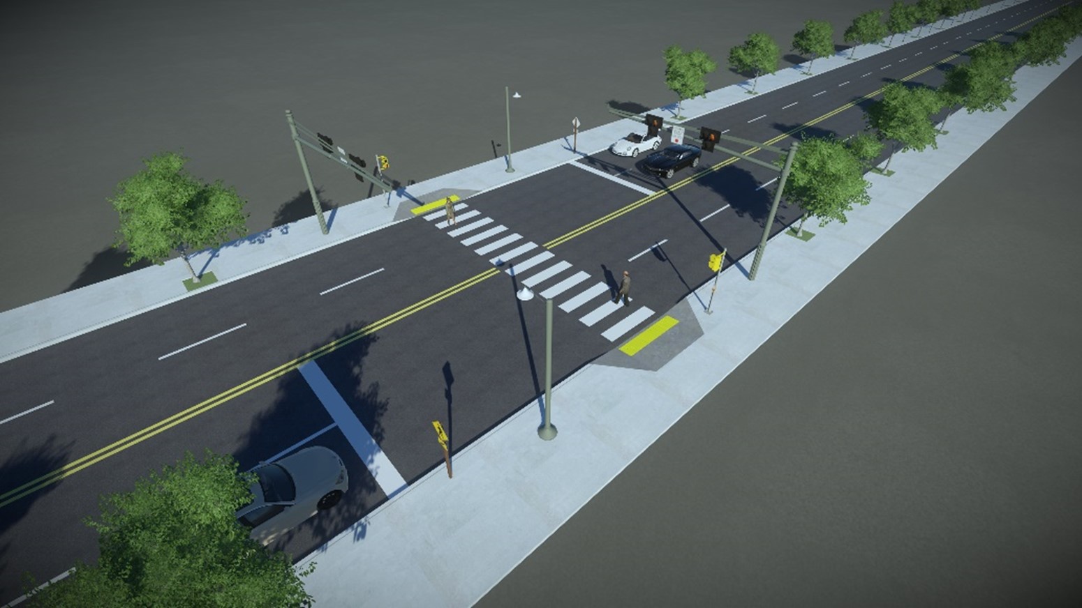 Aerial view of PHB (for illustrative purposes only)
How To Use a PHB
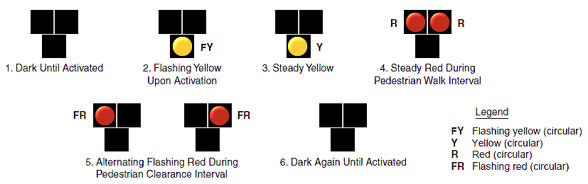
- The PHB rests in dark until a pedestrian activates it via pushbutton or other form of detection.
- Once activated, the beacon displays a sequence of flashing and solid lights that indicate the pedestrian walk interval.
- While the lights are flashing and pedestrians are crossing the roadway, drivers are stopped at a stop bar ahead of the crosswalk.
- When pedestrians have finished crossing the roadway, it is safe for drivers to proceed.
Context
- The PHB is often considered for installation at locations where pedestrians need to cross and vehicle speeds or volumes are high, but where traffic signal warrants are not met.
- These devices have been successfully used at school crossings, parks, senior centers, and other pedestrian crossings on multilane streets.
- PHBs are typically installed at the side of the road or on mast arms over midblock pedestrian crossings.
- PHBs are intended for installation at midblock locations but may be installed at intersections.
- Often used with:
- High-visibility crosswalk markings
- Raised islands
- Advance STOP or YIELD signs and markings
Benefits
- Improved safety: PHBs stop all lanes of traffic, which can reduce pedestrian crashes by up to 55%.
- Traffic compliance: Better stop/driver yield compliance than rectangular rapid flashing beacon (RRFB).
- Increased efficiency: PHBs can be more efficient than full color traffic signals by allowing motorists to proceed during the flashing red display if no pedestrians are present.
- Cost effective: The PHB is often less expensive than a full traffic signal installation.
- Easier approval: Less rigid justification process than a signal warrant.
Policy and Design Guidance
Guidelines are provided for informational purposes only. For detailed design guidance, please refer directly to design manuals and standardslisted below in Resources.
- The PHB should meet the application guidelines provided in the Manual on Uniform Traffic Control Devices for existing or projected pedestrian volumes, and criteria established by VDOT Traffic Engineering Division Memorandum IIM-TE-384, "Pedestrian Crossing Accommodations at Unsignalized Locations"
- PHBs are a candidate treatment for roads with three or more lanes that generally have annual average daily traffic (AADT) above 9,000.
- PHBs should be strongly considered for all midblock and intersection crossings where the roadway speed limits are equal to or greater than 40 miles per hour (mph).
- PHBs should only be installed in conjunction with marked crosswalks and pedestrian countdown signals.
- NCHRP Report 562
 "Guidelines for Pedestrian Crossing Treatments” provides additional information on PHBs.
 - The Virginia Supplement to the MUTCD provides additional guidance on operations and design considerations.
- PHBs, on average, cost $230,000 to $265,000.
Examples of PHBs
 A PHB at a crossing in Fairfax County (VHB)
Ribbon-cutting for the VDOT PHB on Backlick Road in Fairfax County in 2016. VDOT installed the midblock PHB at a high-volume pedestrian crossing location connecting transit stops on either side near an elementary school.
A PHB at a crossing in Alexandria (VHB)
PHB at the intersection of North Van Dorn Street and Maris Avenue in the City of Alexandria. PHBs can be installed at intersections to warn/control the free-flow mainline approaches during a pedestrian actuation, while the minor leg continues to be controlled by the stop sign.
A PHB at a crossing in Vienna (VHB)
PHB on Maple Avenue (Route 123) between Library Lane and Pleasant Street in Vienna, Virginia. This PHB was installed mid-block along a commercialized corridor with heavy foot traffic between the commercial and nearby residential land uses on either side of Maple Avenue.
Resources
Treatment applications and general design guidance:
- VDOT IIM-TE-384.1: Pedestrian Crossing Accommodations at Unsignalized Approaches
- MUTCD Part 4: Highway Traffic Signals
- Virginia State Preferred CMF List
- VA Supplement to the MUTCD Chapter 4
General guidance:
Description
- Raised crosswalks are ramped speed tables that span across the width of the roadway and typically three to six inches above road grade.
- Raised crosswalks are marked as a pedestrian crossing.
- Raised crosswalks make the pedestrian more visible in a driver’s field of vision and allows the pedestrian to cross at the same level as the sidewalk.
- Raised crosswalks reduce vehicle speeds and enhance a pedestrian’s crossing experience.
Aerial view of a raised crosswalk (for illustrative purposes only)
How To Use s Raised Crosswalks
- Raised crosswalks make the pedestrian more visible in a driver’s field of vision and allows the pedestrian to cross at the same level as the crosswalk.
Context
- Raised crosswalks are often installed in campus settings, shopping centers, and pick-up/drop-off zones like airports, schools, and transit centers.
- Raised crosswalks are often used with other crosswalk visibility enhancements.
- Raised crosswalks are often used as a traffic calming device and often with curb extensions.
- Raised crosswalks are typically midblock crossings to bring attention to the pedestrian, but are also often used at entrances to commercial and private drives to slow vehicles, emphasize the crossing conflict, and provide comfort to the pedestrian.
- Typically, raised crosswalks add less than five seconds to emergency vehicle's response time. The safety impacts of this minor delay must be weighed against the safety benefits of this treatment due to the reduced risk of serious pedestrian injury or fatality.
Benefits
- Increased visibility: Raised crosswalks improve visibility of pedestrians within a crosswalk.
- Improved safety: Raised crosswalks can reduce crashes by 45%.
- Reduced speed: Raised crosswalks can reduce 85 percentile speeds to 20 to 30 miles per hour (mph).
- Traffic calming: Raised crosswalks have been documented to reduce volumes by 20%.
- Comfort: Pedestrians can remain at the same elevation while crossing a street without going up and down ramps.
Policy and Design Guidance
Guidelines are provided for informational purposes only. For detailed design guidance, please refer directly to design manuals and standardslisted below in Resources.
- Raised crosswalks are on average 10-feet wide and allow a vehicle’s front and rear wheels to be on the top of the raised crosswalk at the same time.
- Raised crosswalks are three to six inches above road grade.
- Raised crosswalks may be constructed flush with adjacent curb or with pedestrian ramps on both the curb and raised crosswalk.
- Crossings must be fully accessible for those with visual or physical disabilities. Curb ramps and truncated domes that are in compliance with the American with Disabilities Act are added to crossings to make them accessible.
- Raised crosswalks may be installed on two- or three-lane roads with a speed limit of 30 miles per hour (mph) or less and an annual average daily traffic (AADT) below 9,000.
- When designing for raised crosswalks, it is important to consider the impacts on drainage and snowplowing.
- Agencies may also want to consider if the route where the raised crosswalk will be installed includes a bus transit or primary emergency vehicle routes. Larger service vehicles can experience challenges with the vertical deflection which is associated with raised crosswalks.
- Virginia guidance on spacing is approximately 500 feet, with clear visibility of 200 feet, and placement no closer than 200 feet from an intersection.
- Raised crosswalks, on average, cost $5,000 to $8,000.
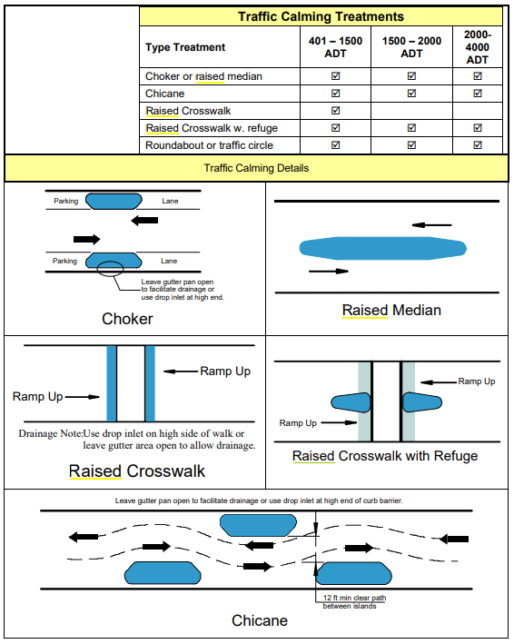
Raised Crosswalks can be used as a tool for traffic calming under VDOT Guidance
Examples of Raised Crosswalks
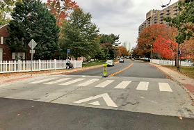 Raised Pedestrian Crossing in Alexandria, VA (FHWA)
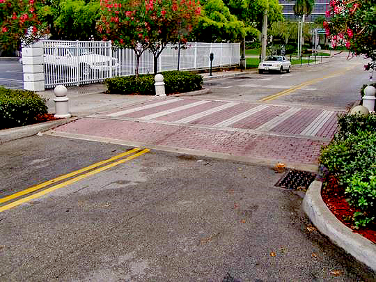 Decorative Raised Pedestrian Crossing (FHWA)
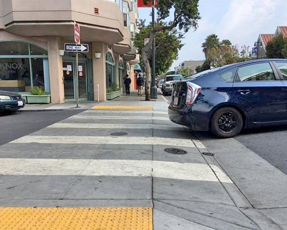 Raised crosswalks slow vehicle speeds (SFMTA)
 Setback raised crosswalk
 Curb Extension Raised Crosswalk
Resources
Treatment applications and general design guidance:
- MUTCD Chapter 3B. Pavement and Curb Markings
- FHWA Raised Crosswalks Tech Sheet
- Appendix B Subdivision Street Design Guidance
- VA Supplement to the MUTCD 2011 Section 3B
General guidance
Intersection Safety Treatments
Description
Resource Links
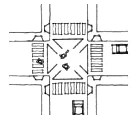
- Left-turn hardening refers to the use of modular curbs, vertical delineators, and striping at intersections to reduce left-turning speeds and to prevent “corner cutting."
- Common left-turn hardening strategies include:
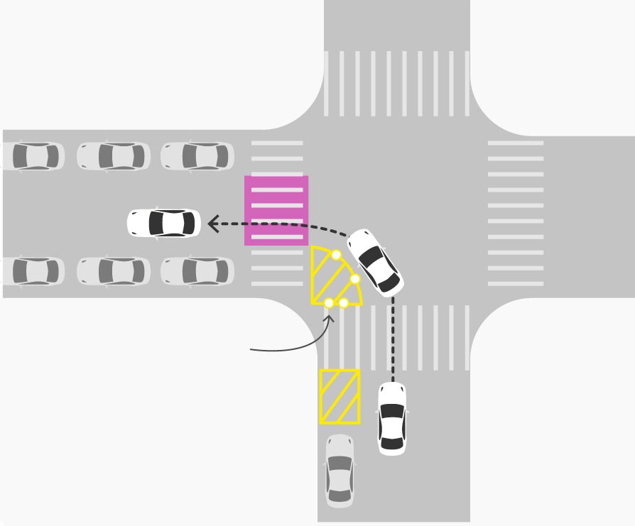
- Centerline hardening, which refers to the placement of modular curbs where the centerline meets the intersection, and
- Slow turn wedges, which use striping and delineators at intersection corners to slow left-turning vehicles at intersections between two one-way streets.
- Left-turn hardening emphasizes the separation between travel directions, guides vehicles into the receiving lane, and reduces turning speeds, reducing the conflict zone between turning vehicles and people biking and walking.
- Left-turn hardening is often combined with other visibility improvements such as the removal of parking near the intersection.
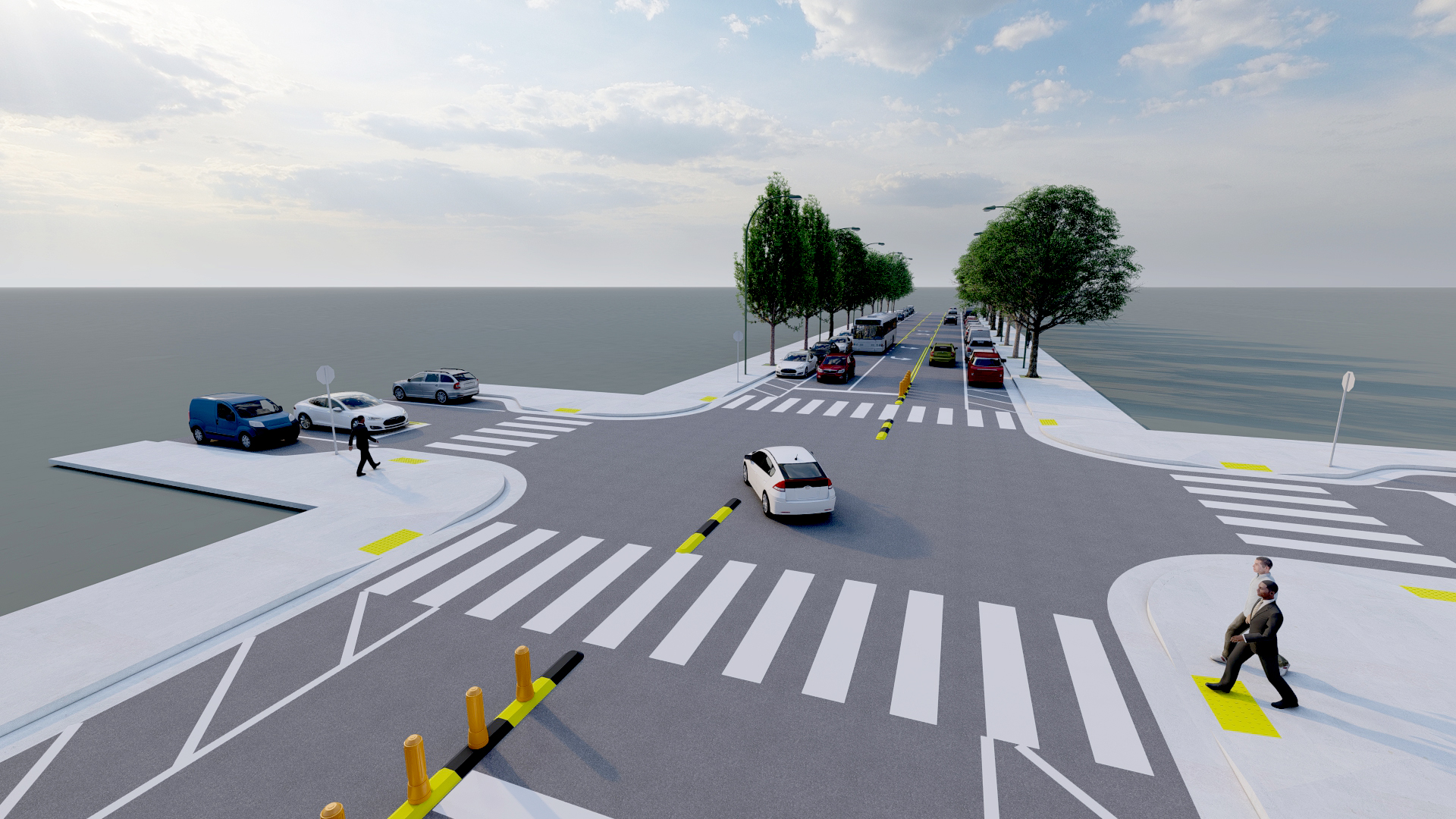
Left-turn hardening helps slow left-turning vehicles and
reduce conflicts with crossing pedestrians (for illustrative purposes only)
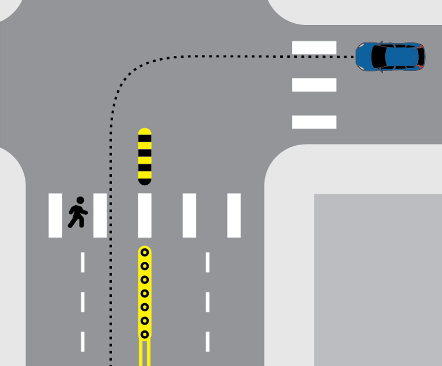
Slow-turn Wedge (Quartz)
How To Use Left-Turn Hardening
- Left-turn hardening does not change how motorists, pedestrians, or cyclists should navigate through an intersection; it simply helps reduce the speeds of left-turning vehicles.
Context
- Left-turn hardening is often installed at intersections where a minor street intersects with a major street, with the elements addressing left-turns from the minor street onto the major street.
- Slow turn wedges are often installed at intersections of two one-way streets.
- Left-turn hardening is especially useful at intersections with high volumes of pedestrians and where speeds of left-turning vehicles are an issue.
Benefits
- Improved safety: Left-turn hardening reduces conflict zones between vehicles and people walking or biking. In the state of Virginia, 18% of injuries to pedestrians are a result of collisions with left-turning vehicles.
- Safer speeds: By reducing turning radii, left-turn hardening forces drivers to slow down as they make turns.
Policy and Design Guidance
Guidelines are provided for informational purposes only. For detailed design guidance, please refer directly to design manuals and standards listed below in Resources.
- Hardened centerlines are installed in line with the centerline approaching an intersection and typically include modular curbs and vertical delineators. These elements may extend to the stop bar, to the crosswalk, or farther into the intersection.
- Slow turn wedges are installed at the corners of intersections in line with on-street parking and on the far side of crosswalks. They typically include pavement markings and vertical delineators.
- Left-turn hardening elements may be installed without vertical elements or with adjusted vertical elements to accommodate larger vehicles and/or sight lines.
- Flexible delineators and modular medians are designed to be mountable and are not considered rigid objects, so clear zone requirements do not apply.
- The appropriate size and setback of left-turn hardening elements is determined via a swept path analysis of the intersection, based on the largest vehicle that makes the left-turn turn at least a few times a day (design vehicle). While the design vehicle may traverse mountable elements, standard vehicles should be able to turn without doing so.
- Left-turn hardening treatments may be adjusted at intersections with nearside bus stops, peak-hour parking restrictions, high volumes of heavy vehicle traffic, bicycle lanes, or skewed geometry to accommodate design vehicles, transit vehicles, or other roadway elements.
- Consider winter maintenance when installing left-turn hardening elements.
- Left-turn hardening elements typically cost $2,000-$4,500 per intersection
Examples of Left-Turn Hardening
 Left-turn hardening at the intersection of Seminary road and Fort Williams Parkway in Alexandria, VA (Kittelson & Associates, Inc.)
As part of a Complete Streets project, bicycle lanes and pedestrian enhancements were installed on Seminary Road in Alexandria, VA to provide the most protection possible on this heavily trafficked corridor. At the intersection of Seminary Road and Fort Williams Parkway, a mountable hardened centerline was installed to prevent "corner cutting" and reduce the speed of turning vehicles.
 Left-turn hardening at the intersection of Grand Avenue and West Burnside Avenue in the Bronx in New York ( Google Earth )
In 2016, the New York City DOT and Vision Zero NYC produced a Left Turn Study Action plan to address a history of crashes caused by left-turning vehicles. As part of this plan, slow turn wedges and/or hardened centerlines were installed at over 408 pilot intersections. At intersections where these treatments were implemented, average left-turn speeds have decreased by 53% and pedestrian injuries have decreased by 20%.
 Left-turn hardening at the intersection of 11 th Street and I Street,
SE in Washington, D.C. ( Google Earth )
Following NYC's example, the District Department of Transportation and Vision Zero Washington D.C. began a left-turn traffic calming campaign in 2018, in which 44 locations were identified for improvement. A study found that the average number of conflicts between vehicles and pedestrians, as well as the average speed, fell at locations where the hardening infrastructure was installed.
Resources
Treatment applications and general design guidance:
Geometric design guidance for Virginia:
Pavement markings, signage, and spacing:
Examples from other states and districts:
Description
Resource Links
- This treatment focuses on signal timing and phasing strategies that may assist speed management at intersections. These strategies can include implementing traffic controller strategies to alter a driver’s behavior and therefore improve conditions for pedestrians and bicyclists. Three such treatments include dwelling on red, pedestrian recall, and signal coordination based on safe speeds.
- Dwell-on-Red is a treatment that involves signals reverting to an all-red phase when there is no vehicular traffic demand, thereby reducing nighttime speeding when volumes are typically low.
- Pedestrian Recall is a treatment that involves a pedestrian phase activating every signal cycle regardless of pedestrian presence. This treatment can increase driver expectation of the pedestrian signal phase.
- Signal coordination is typically based on observed 85th percentile vehicle speeds, which may be higher than appropriate safe speeds. Instead, the corridor progression can be designed for a safe speed (i.e., the posted speed limit) and that speed can be communicated to drivers.
- These signal timing strategies work in concert with physical speed management countermeasures like pedestrian refuge islands, raised crossings, curb extensions, or other pavement markings to influence lower vehicle speeds and improve the conditions for pedestrians and bicyclists. All these strategies work together to reduce pedestrian exposure to vehicles or prompt a psychological response in motorists to choose lower speeds. VDOT describes these physical countermeasures in detail on other treatment pages.

An aerial view of curb extensions and a pedestrian refuge island, two examples of physical speed management countermeasures (for illustrative purposes only)
How To Manage Speed via Signal Timing Strategies
- Dwell-on-red and pedestrian recall can be programmed by engineers to improve speed management and to create a consistent expectation from drivers of a pedestrian phase's presence.
- Traffic engineers can program signals to discourage speeding - vehicles traveling at the engineered (and communicated) progression speed will be more likely to arrive at signals during the green phase, whereas those vehicles traveling at higher speeds will stop more frequently at subsequent traffic signals. This should encourage drivers to select the speed that will decrease their likelihood of stopping at successive signals, thereby improving speed management.
- Long signal cycles result in long waits to receive a Walk signal and can cause pedestrians to disregard signals. Engineers can shorten cycles to reduce delay to pedestrians and increase the frequency of crossing opportunities.
- In some contexts, engineers may program signals based on typical bicycle speeds to promote slower vehicular speeds and for continuous progression along the corridor for both vehicles and cyclists with fewer stops.
Context
- Signal timing strategies that can improve speed management are often implemented at intersections with higher volumes of vehicle, pedestrian, and bicyclist traffic.
- Dwell-on-red is often used during late night periods when impairment crashes are more prevalent and there would be a minimal impact on traffic congestion.
Benefits
- Safer speeds: Speed management slows speeding traffic and reduces risk for pedestrians and bicyclists.
- Cost effective: Signal timing strategies to influence speed are primarily low cost. Costs are typically limited to engineering the signal timing plan and inputting it into the controller.
Policy and Design Guidance
Guidelines are provided for informational purposes only. For detailed design guidance, please refer directly to design manuals and standards listed below in Resources.
- Signal timing should meet the guidelines provided in the Virginia Supplement to the Manual on Uniform Traffic Control Devices.
- For additional strategies related to traffic calming and speed management, refer to:
- VDOT's Neighborhood Traffic Programs
- $200 Speeding Fine Program
- Cut Through Traffic and Watch for Children Sign Program
- VDOT's Policy for Speed Display Signs
Examples of Speed Management via Signal Timing Strategies

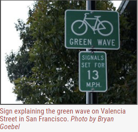 Example of a street sign in San Francisco explaining that the signal timings are set for bicyclist progression speeds.
Resources
General guidance:
Description
Resource Links
-
Pedestrian signal control treatments can include protected pedestrian signal phases, two-stage directional crossings, scramble or exclusive pedestrian phasing, and leading pedestrian intervals (LPI).
- A protected pedestrian signal phase is when all conflicting turning vehicular movements are protected-only and do not occur during the pedestrian signal phase. Parallel vehicular movements may occur concurrently with the pedestrian crossing.
-
A two-stage signal-controlled directional crossing is designed to force pedestrians to cross the roadway in two separate movements. The z-configuration orients the pedestrian to bring their attention to the two separate crossings and to view oncoming vehicles while in the median refuge area walking from one crossing to the next.
-
A pedestrian scramble is an exclusive pedestrian phase that stops all traffic at an intersection and allows pedestrians to cross in any direction (including diagonal).
-
An LPI gives pedestrians three to seven seconds to begin entering the crosswalk before conflicting vehicles are given the green light. Turning vehicles must yield to the pedestrians in the crosswalk and may proceed once the crosswalk is clear.

An aerial view of a two-stage directional crossing, one example of a Pedestrian Signal Control Treatment (for illustrative purposes only)
How to use Pedestrian Signal Control Treatments
- A protected pedestrian signal phase does not require any additional action from the pedestrian. The pedestrian may need to activate the crossing as normal before receiving the green indication and entering the crosswalk. Drivers are not allowed to turn across the crosswalk during the pedestrian phase.
-
During a two-stage signal-controlled directional crossing, the pedestrian crosses to the pedestrian refuge island in the median and waits in the median for a second pedestrian phase to cross the second leg.
-
To activate a pedestrian scramble, a pedestrian may need to push a button or a sensor may be used to detect the presence of pedestrians. The pedestrian scramble stops all vehicular traffic and allows the pedestrians to cross within the marked crosswalks. Pedestrians can cross to their left or right or diagonally across the intersection.
-
During an LPI, the pedestrians begin crossing in the crosswalk while the traffic is stopped. Through and turning traffic are subsequently given the green light, and the traffic yields to pedestrians already in the crosswalk.
Context
- A protected pedestrian signal phase allows pedestrians to cross while conflicting vehicles are stopped. Pedestrians can look to the pedestrian signal heads for indication of when it is safe to cross.
-
A two-stage signal-controlled directional crossing is best implemented in mid-block areas with multiple lanes of oncoming traffic, but may be used at signal-controlled intersections or across a multilane roundabout leg.
-
A pedestrian scramble is most commonly used in areas with extremely high surges of pedestrian traffic such as downtowns, university campuses, and sports arenas.
-
LPIs are typically installed in areas with numerous pedestrian crashes, high pedestrian volumes, high volumes of school-aged children or older adults, or where turning vehicles make it difficult for pedestrians to begin a crossing.
- Pedestrian signal control treatments are often used with:
- Crosswalk visibility enhancements
- Curb extensions (where road width allows)
- Right turn on red (RTOR) restrictions
- Accessible pedestrian signals
Benefits
- Improved safety:
- Protected pedestrian signal phases: While there is not a comprehensive crash modification factor for this treatment, crash modification factors indicate that a conversion of permissive left-turn phasing to protected only or protected/permissive phasing can reduce pedestrian crashes by 28%.
- Two-stage directional crossings: While there is no published crash modification factor for a two-stage pedestrian movement, pedestrian refuge islands, which are a key component of this treatment, can reduce pedestrian crashes by 32%.
- Exclusive pedestrian phase: An exclusive pedestrian phase can reduce crashes by 51%.
- Leading pedestrian interval: LPIs can reduce pedestrian crashes by 13%.
- Improved comfort: FHWA’s connected networks approach includes safe and comfortable facilities.
Policy and Design Guidance
Guidelines are provided for informational purposes only. For detailed design guidance, please refer directly to design manuals and standards listed below in Resources.
-
Pedestrian refuge islands - as part of two-stage directional crossings - should meet the application guidelines provided in the VDOT Traffic Engineering Division Memorandum IIM-TE-384 Attachment A, “Unsignalized Marked Crosswalk Standards.”
- The pedestrian walkway through a refuge island shall be at least 5-feet wide and at least 6-feet long.
-
Two-stage directional crossings can be installed at any signal-controlled intersection approach. Additionally, they might be installed on unsignalized intersection approaches or in midblock locations on roadway cross-sections with four or more lanes, a speed limit of at least 35 miles per hour (mph), or an annual average daily traffic (AADT) over 9,000.
-
The Manual on Uniform Traffic Control Devices (MUTCD) says an LPI should last at least three seconds to ensure that pedestrians are able to cross at least one travel lane.
-
LPIs should be accompanied by Accessible Pedestrian Signals (APS), which help visually impaired pedestrians navigate intersections using audible tones, speech messages, and vibrotactile feedback. IIM-338 requires APS to be installed when alteration activities take place at a signalized intersection.
-
The two-stage directional crossing requires passive pedestrian detection or pushbuttons in the refuge island.
-
Costs of these treatments can vary.
- Installing pedestrian signal phasing when the crossings are currently unsignalized can range from $65,000 to $250,000 depending on intersection characteristics, existing signal controller capabilities, and existing signal control infrastructure.
- LPIs and exclusive pedestrian phases can range from $500 for controller / cabinet setting changes only to several thousand dollars if an engineering study or crosswalk markings are also required.
- A two-stage directional pedestrian crossing can range from $2,000 with no new pedestrian signal infrastructure to over $40,000 with new pedestrian signal infrastructure. An additional cost variable is the length of the refuge island.
Examples of Pedestrian Signal Control Treatments
 Pedestrian signal phase at an intersection in Los Angeles, CA. The conflicting right-turn phase is controlled with an arrow, which prohibits that movement during the pedestrian phase.
 Diagram of two-directional crossing (Federal Highway Administration University Course on Bicycle and Pedestrian Transportation, FHWA)
 ) Pedestrian crosses during an LPI phase (FHWA)
Pedestrian crosses during an LPI phase (FHWA)
 Pedestrian scramble sketch (Pedestrian Facilities Users Guide – Providing Safety and Mobility, FHWA)
 An intersection in Alexandria, VA with LPIs. (Patch)
The City of Alexandria, VA installed LPIs on signals at 17 locations as part of the City’s Vision Zero plan. The locations undergoing the changes were identified as high-crash intersections or corridors.
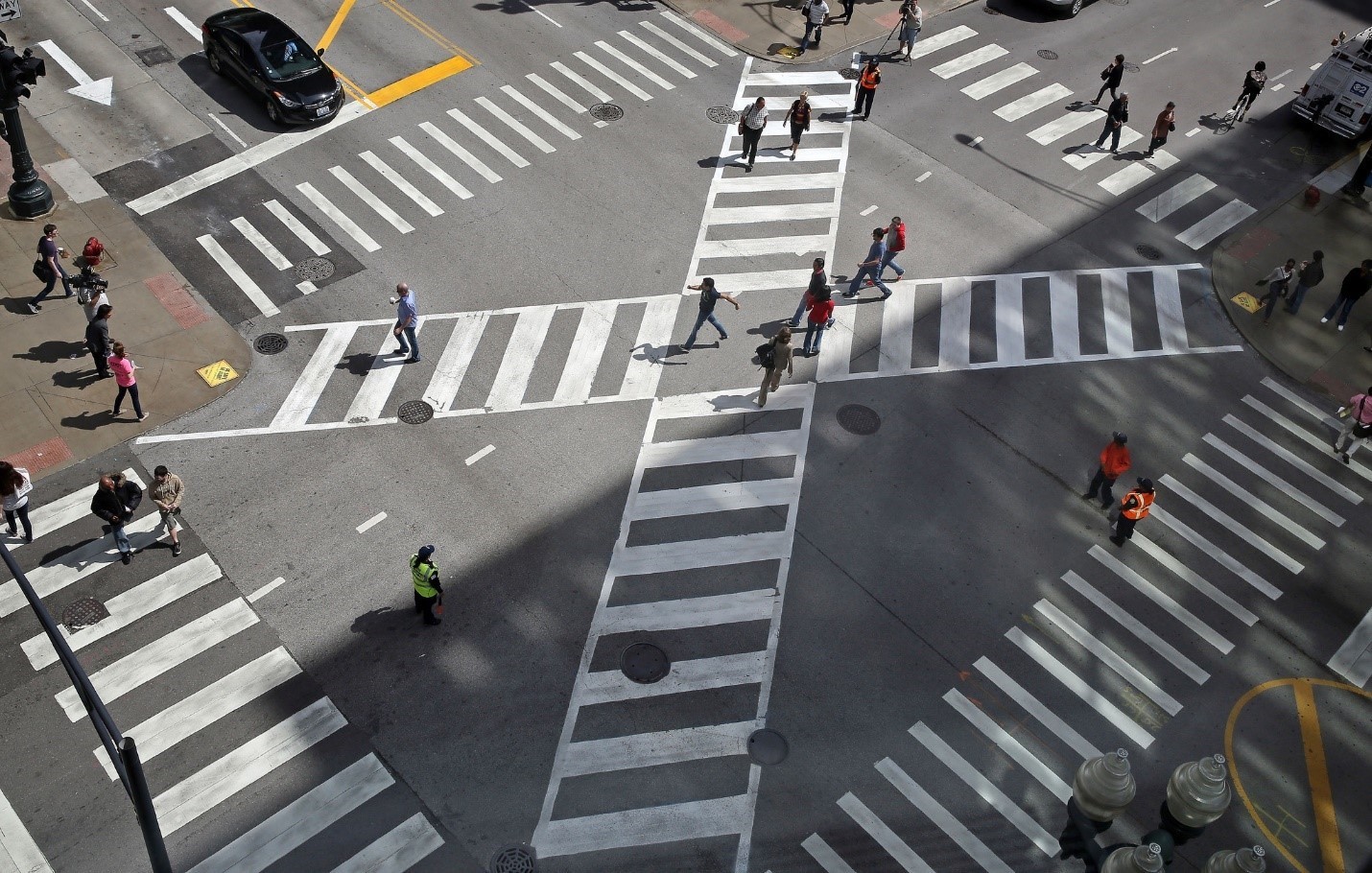 A pedestrian scramble in Chicago, IL. (Chicago Tribune)
Pedestrian scrambles are relatively new to the U.S. Phoenix, Chicago, and Washington, D.C. are some of the cities that have installed pedestrian scrambles. The City of Chicago installed this pedestrian scramble at State Street and Jackson Boulevard to give pedestrians a head-start when crossing the streets. This countermeasure reduces the number of conflicts between pedestrians and turning vehicles.
Resources
Treatment applications and general design guidance:
- VDOT IIM-TE-384: Pedestrian Crossing Accommodations at Unsignalized Locations"
- VDOT Traffic Engineering Design Manual
- Virginia Supplement to the MUTCD Part 4
General guidance:
- FHWA Guide for Improving Pedestrian Safety at Uncontrolled Crossing Locations
- FHWA Pedestrian Refuge Island Tech Sheet
- FHWA LPI Tech Sheet
- FHWA Facilities User Guide - Providing Safety and Mobility
- VDOT Pedestrian Safety Action Plan
- NACTO Urban Street Design Guidelines - Pedestrian Safety Islands
- FHWA Safety Evaluation of Leading Pedestrian Intervals on Pedestrian Safety
Description
Resource Links
-
Smart lighting, or adaptive lighting, is a type of pedestrian device that once activated, increases a pedestrian’s or bicyclist’s visibility to drivers through illumination.
-
Smart lighting can be more cost efficient than static lighting by having the lights be dimmed or off except when a pedestrian is detected.
-
Smart lighting provides an alternative to static lighting in locations with light pollution concerns, especially in urban residential environments, by limiting illumination only to occasions when pedestrians are present.
An aerial view rendering of smart lighting (for illustrative purposes only)
How to use Smart Lighting
-
Smart Lighting does not illuminate until activated through passive automated detection technologies. Once activated, the lights turn on and may increase in intensity, illuminating the pedestrian’s or bicyclist’s crossing or path, helping motorists see a pedestrian next to or in the crosswalk.
-
Before a pedestrian enters the crosswalk, the pedestrian should confirm vehicles are slowing or stopping. Pedestrians should continue to scan both directions of the roadway while crossing.
Context
- Smart Lighting is often considered for installation in combination with crosswalk visibility improvements and signing improvements.
- Smart Lighting is suitable for installation at all crosswalks.
Benefits
- Increased yielding rates: Supplemental lighting for a crosswalk can increase driver yielding.
- Increased visibility: Smart lighting can increase pedestrian and bicyclist visibility and reduce the glare for drivers.
Policy and Design Guidance
Guidelines are provided for informational purposes only. For detailed design guidance, please refer directly to design manuals and standards listed below in Resources.
-
Design guidance varies depending on type, detection, and electrical service source.
-
Smart lighting is typically hardwire powered, but as solar technology continues to comprove, solar-powered smart lighting may be feasible.
-
Passive detection is recommended over pushbutton application, as drivers may grow conditioned to only expect pedestrians in the crosswalk at night when the lights are on, increasing risk for a pedestrian who doesn't push the button. This also ensures that the lights don't activate during daytime when they provide little benefit.
-
Smart lighting can vary considerably depending on type, scale, detection type, and electrical service, among other factors. Cost may range from $15,000 to $150,000.
Examples of Smart Lighting

The city of Copenhagen, Denmark installed overhead dynamic lighting at this pedestrian crossing using radar sensors to detect the crossing pedestrian. (Lighting Metropolis)
Resources
Treatment applications and general design guidance:
- VDOT IIM-TE-390: Light Emitting Diode (LED) Exterior Lighting
- FHWA Design Criteria for Adaptive Roadway Lighting
General guidance:
Bicycle Facilities
Description
Resource Links
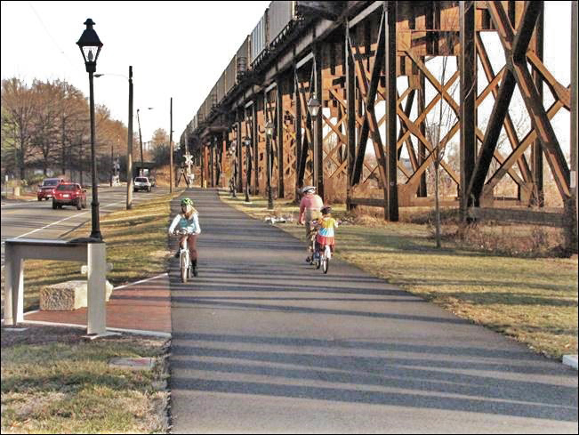
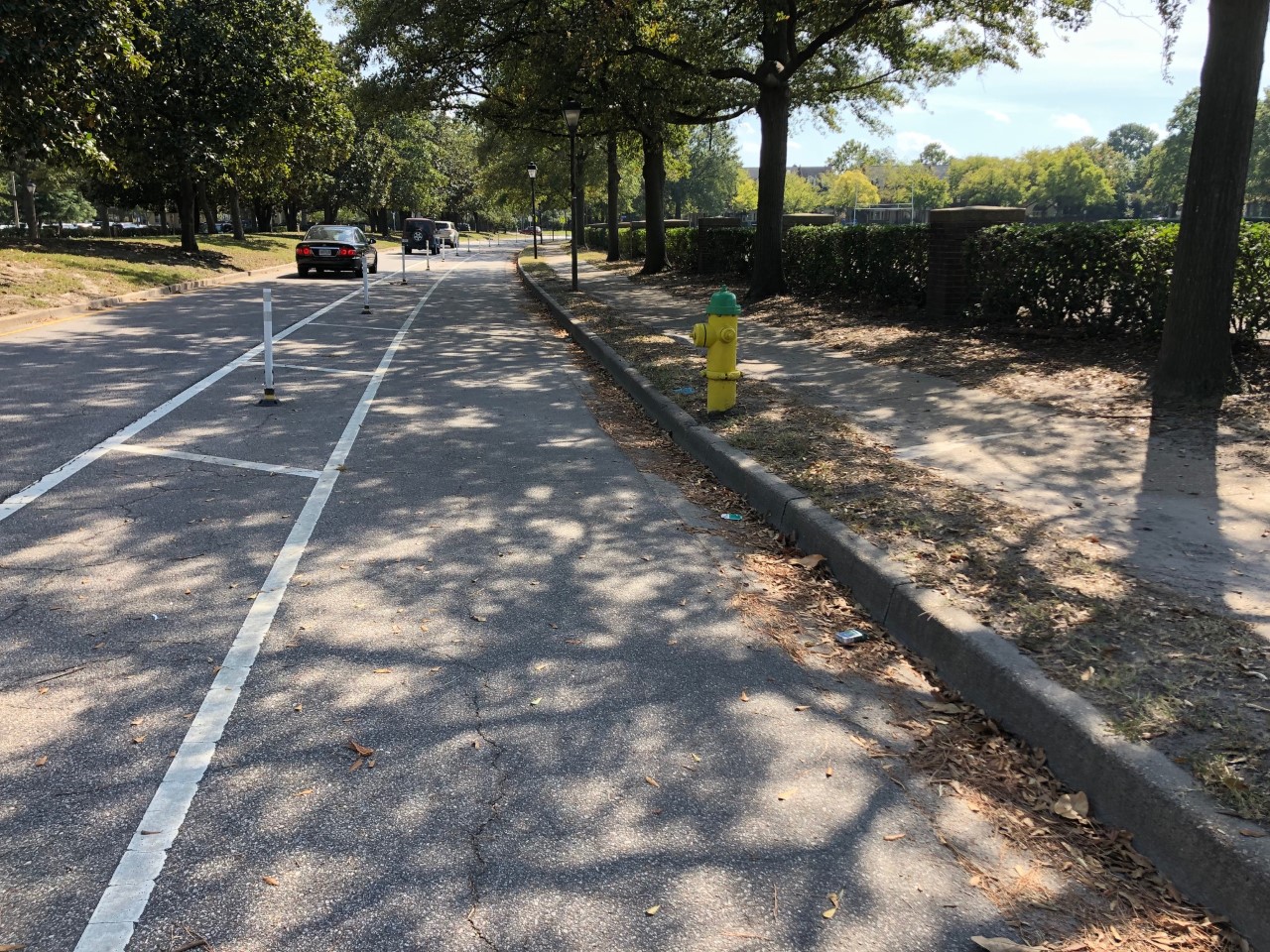
- Side paths are shared use paths that run parallel and adjacent to a roadway.
- Side paths separate non-motorized users from the roadway by a horizontal buffer or a barrier.
- Side paths serve as an extension of the bike and pedestrian network. They provide opportunities for bicyclists and pedestrians to travel separated from motor vehicles. Some Side paths may also allow equestrians.
Aerial view of a side path (for illustrative purposes only)
How To Use a Side Path
- When using a side path, pedestrians and bicyclists should stay to the right except when passing on the left.
Context
- Side paths can be installed in urban and rural areas.
- Side paths should not be installed on corridors with frequent driveways.
Benefits
- Improved safety: Side paths provide additional separation from the roadway and can decrease the likelihood of mid-block collisions with pedestrians and bicyclists
- Improved comfort: Side paths and SUPs are more accommodating to bicyclists of all comfort levels and abilities as compared to traditional bike lanes or facilities that require bicyclists to ride in mixed traffic.
- Increased connectivity: Side paths complete networks where high-speed roads provide the only available corridor
Policy and Design Guidance
Guidelines are provided for informational purposes only. For detailed design guidance, please refer directly to design manuals and standards listed below in Resources.
- Side paths are typically at least 10 feet wide; however, 12-foot width is preferred. Side paths may be narrowed to eight feet where right of way or engineering constraints prohibit 10-foot width.
- When the distance between the roadway pavement edge and the side path is less than five feet, a physical barrier is required.
- Side paths require a minimum of eight feet separation from the roadway face of curb to provide lateral clearance for signs to both the road and the path. If signs are placed to the outside, the minimum distance between edge of path and the face of curb is three feet.
- When the side path is adjacent to a water feature or a slope greater than or equal to 3:1, a 5-foot gap is required between the edge of path and the hazard. If the distance is less than five feet, a physical barrier is required.
- At approaches to cross streets, the side path should either bend in to be adjacent to the parallel roadway for maximum visibility of all users or bend away from the parallel road to be far enough from the road intersection so that vehicles can turn from the parallel road with enough room to be completely out of the intersection before yielding to the side path crossing.
- To reduce the risk of collisions, the 2012 AASHTO Bike Guide recommends:
- Reducing the number of driveways.
- Designing intersections to reduce speeds.
- Maintaining sight distance for all users.
- Side paths are required to be accessible by all users, including those that may be vision and/or mobility impaired.
- Stop signs should be used sparingly on side paths. Stop signs typically are not recommended where the side path intersects with a low-volume entrance or low-volume/low-speed subdivision street.
- Side paths vary in cost depending on the materials used, right-of-way purchased, and other factors. Average construction costs for paved side paths can range from $250,000 to $5,000,000 per mile depending on terrain, structures (e.g., bridges, sound barriers, etc.), environmental impact mitigation, number and type of road crossings, amenities, and other design criteria. Unpaved side paths can be constructed for as little as $30,000 per mile.
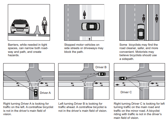
Side path conflicts (Guide for the Development of Bicycle Facilities, AASHTO)
Examples of Side Paths
 Proposed side path in Virginia Beach (City of Virginia Beach)
 Side path in Arlington, Virginia
 Side path in Richmond, Virginia
Resources
Treatment applications and general design guidance:
- Small Town and Rural Design Guide
- AASHTO Guide for the Development of Bicycle Facilities
- Virginia Supplement to the MUTCD, Part 9
- Virginia Supplement to the MUTCD
- VDOT Complete Streets
- VDOT Road Design Manual, Appendix A
General guidance:
Rural applications:
Description
Resource Links
- Shared use paths are facilities that are meant solely for pedestrians and non-motorized vehicles such as bicycles and e-bicycles. Some shared use paths allow equestrian users. Motorized vehicles are typically prohibited (except for maintenance vehicles). Shared use paths are intended for use by bicyclists and pedestrians of all abilities, and therefore are typically relatively level and use a relatively smooth surface such as asphalt or fine aggregate.
- Shared use paths are physically separated from motor vehicle traffic.
- Shared use paths may or may not be aligned parallel to the highway, and if they are parallel to the highway may be in or out of the highway right-of-way.
- Shared use paths are designed for two-way travel.
- Shared use paths serve as an extension of the multimodal network for pedestrians and bicyclists.

Aerial view of shared use path (for illustrative purposes only)
How to Use a Shared Use Path
- When using a shared use path, pedestrians and bicyclists should stay to the right except when passing on the left.
- Users are required by state code to give an audible warning when passing.
Context
- Shared use paths often parallel other geographic features such as waterways, former or active rail roads, utility corridors, or highways.
- Shared use paths serve as an extension to sidewalks and on-street bicycle facilities.
- Shared use paths are not the same as trails, which have different design guidelines. VDOT uses the word “trails” to refer to natural surface paths.
- Shared use paths often attract recreational off-roadway cycling. Shared use paths in urban areas can also become an important commuter option, with some Virginia shared use paths serving thousands of commuters a day.
Benefits
- Improved safety: Shared use paths separate non-motorized users from motorized traffic and can reduce certain crash types.
- Aesthetic: Shared use paths offer opportunities for recreational cycling and commuting and can highlight areas with scenic views.
- Increased comfort: Pedestrians and bicyclists can use the facility separated from the noise and exhaust of motor vehicle traffic.
- Alternative mode choice: Some shared use paths provide a mobility choice other than driving – reducing greenhouse gas emissions, encouraging healthier lifestyles, and providing a needed option for users who do not own their own vehicle and/or may have limited public transit options.
- Improved public health: By encouraging recreational or commuter cycling, shared use paths also encourage more active lifestyles for path users.
Policy and Design Guidance
Guidelines are provided for informational purposes only. For detailed design guidance, please refer directly to design manuals and standards listed below in Resources.
- Shared use paths require careful design to ensure safe crossings and interactions between the different nonmotorized users.
- Shared use paths are typically at least 10 feet wide with a 2-foot shoulder (maximum 6:1 slope) and a minimum 3-foot clearance between edge of path to lateral obstructions. Some older shared use paths are only 8 feet wide, but for new shared used paths widths less than 10 feet should be avoided except where constraints preclude a wider width.
- When the shared use path is adjacent to a water feature or a slope greater than or equal to 3:1, a 5-foot gap is required between the edge of path and the hazard. If the distance is less than five feet, a physical barrier is required.
- Shared use paths typically have a maximum 5% grade and a 2% cross slope.
- Shared use paths have a typical design speed, on average, of 18 mph. In areas with a downgrade greater than 6%, a design speed of 30 mph may be used.
- Shared use paths vary in cost depending on the materials used, right-of-way purchased, and other factors. Average construction costs for paved shared use paths can range from $250,000 to $5,000,000 per mile depending on terrain, structures (e.g., bridges, sound barriers, etc.), environmental impact mitigation, number and type of road crossings, amenities, and other design criteria. Unpaved shared use paths can be constructed for as little as $30,000 per mile.

Design details for a shared use path showing typical dimensions and sign placement
(VDOT Road Design Manual)
Examples of Shared Use Paths
 Custis Trail in Arlington, VA (Krista Nordback)
 Scenic shared use path in Virginia
 Southern Tip Hike and Bike Trail in Northampton County, VA (VHB)
Resources
Treatment applications and general design guidance:
- FHWA Shared Use Paths
- VDOT Network for Success Local Programs Workshop
- MUTCD Part 9
- VDOT Road Design Manual
- BIKE SAFE
- Virginia Supplement to the MUTCD
General guidance:
- Share VA Roads
- FHWA Evaluation of Safety, Design, and Operation of Shared-Use Paths
- AASHTO Guide for the Development of Bike Facilities
- FHWA Small Town and Rural Multimodal Networks
- AASHTO Policy on Geometric Design of Highways and Streets, 7th Edition
- AASHTO Guide for the Planning, Design, and Operation of Pedestrian Facilities
- NACTO Urban Walkable Thoroughfares
Description
Resource Links
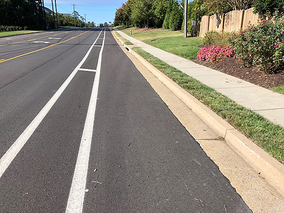
- Traditional bicycle lanes are one-way facilities running along the curb, shoulder, or on-street parking lane that carry bicycle traffic in the same direction as motor vehicle traffic.
- A traditional bicycle lane is designated by pavement markings and signing for the preferential use of bicycles.
- Traditional bicycle lanes have horizontal separation (i.e. pavement markings, such as solid white lines) but do not have vertical separation between the bike lane and the vehicle travel lane and/or parking lane.
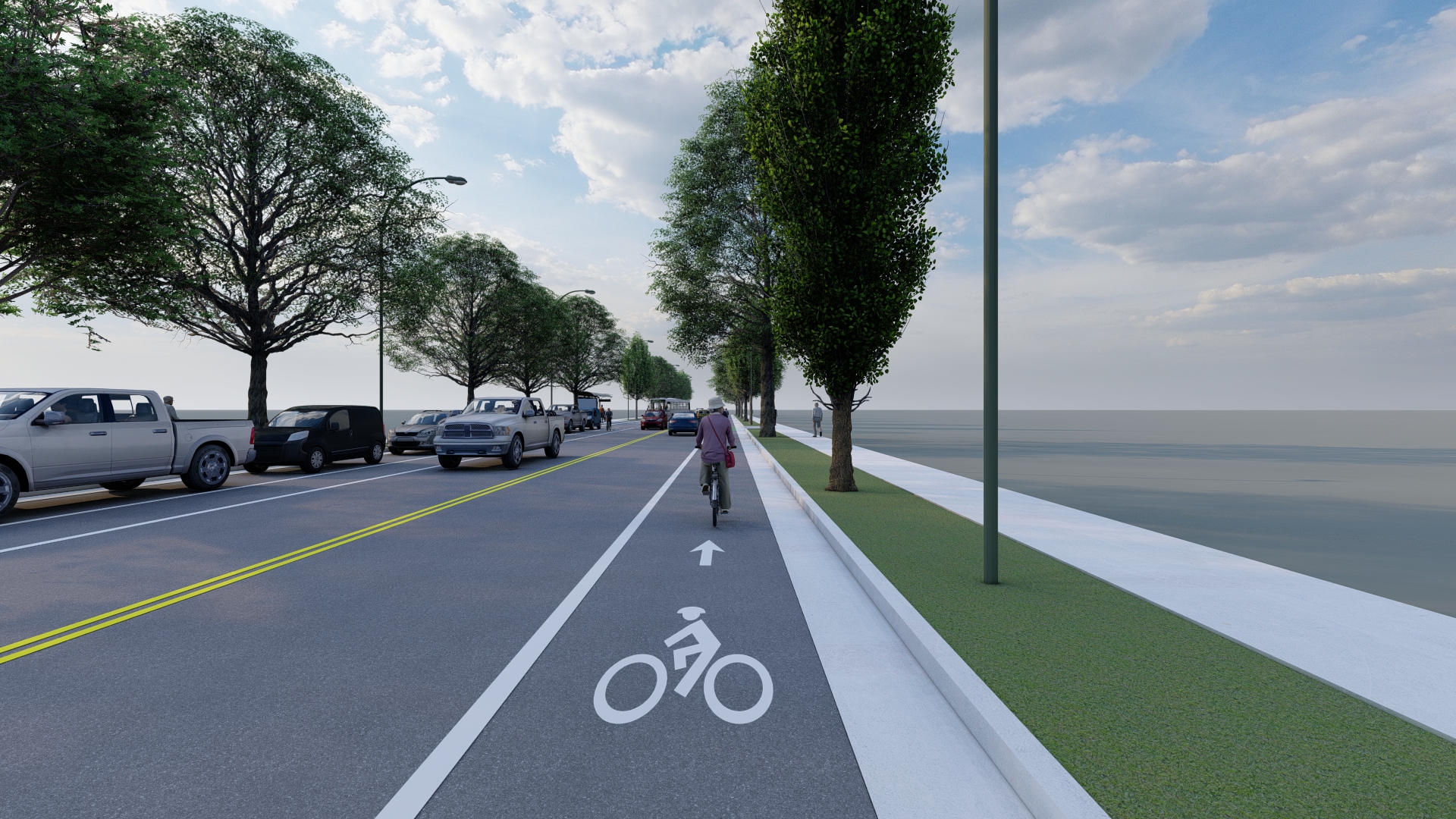
A traditional bicycle lane running along on-street parking (for illustrative purposes only)
How To Use a Traditional Bicycle Lane
-
As they ride, bicyclists should be aware of turning motor vehicles and opening doors. A bicyclist may leave a traditional bicycle lane to pass other users, make turns, or avoid obstacles.
-
Drivers may cross through a traditional bicycle lane only to make a right turn or to enter/exit a parking spot. When making a right turn or accessing parking, drivers are required to yield to bike traffic, then merge into the bike lane and turn from the curb or park. In these instances, the bicyclist should pass on the left as the driver merges to the right.
-
Drivers may not drive or park in a traditional bicycle lane unless weather conditions, an accident, or another emergency situation requires them to do so.
Context
- A traditional bicycle lane is often installed on streets with moderate average daily traffic, speed limits below 35 mph, and with high transit vehicle volumes. On low speed streets with higher volumes, a traditional bicycle lane is preferred over a wide curb lane.
- On streets with higher traffic volumes, steep grades, high truck traffic, or high parking turnover, treatments that provide greater physical separation should be considered.
Benefits
- Improved safety: Provides separation from motor vehicles, establishes predictable riding behavior, visually reminds motorists of bicyclists’ presence and right of way.
- Improved comfort: Allows bicyclists to travel at their preferred speed.
- Traffic compliance: Reduces wrong way riding.
- Increased efficiency: Increases capacity of the roadway.
Policy and Design Guidance
Guidelines are provided for informational purposes only. For detailed design guidance, please refer directly to the design manuals and standards listed below in Resources.
- Wider bicycle lanes provide higher levels of capacity and comfort and they facilitate safer passing and side-by-side riding without needing to leave the bicycle lane.
- Care should be taken to assure the width of the “rideable surface” is adequate; the measured width of the lane should take into account possible obstacles such as gutters, as well as clearance from vertical elements such as curbs or guardrails.
- Generally, traditional bicycle lanes are positioned on the right side of the street unless the street is one-way and designated as a Bike Boulevard.
- Bike lanes should have a smooth riding surface and be free of raised utility covers and debris.
- A single solid white line is often used to demarcate the lane and minimize conflicts with parked cars or adjacent vehicles. Lane markings may be dashed through intersections or other merging areas.
- Green pavement markings may be used to increase the visibility of the bicycle lane.
- Bicycle lane pavement markings should be periodically stenciled in the bicycle lane, especially following intersections.
- Traditional bicycle lanes typically cost $85,000 - $320,000 per mile (Low end of cost estimates assumes only thermoplastic lane lines and signage. High end of cost estimates assumes all above and continuous application of green pavement markings in conflict areas.)
Examples of Traditional Bicycle Lanes
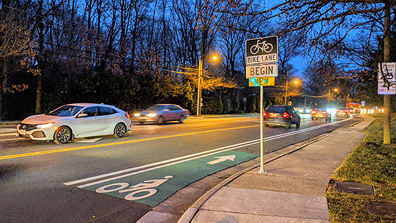
 A traditional bicycle lane on Route 29 in Amherst, VA
The Town of Amherst converted overly wide shoulders and travel lanes on Route 29 to bike lanes through a simple "lane diet. "This concept did not remove any roadway capacity, but reduced the lane widths and re-allocated space to provide bicycle facilities.
 Before and after a traditional bicycle lane was installed on Lawyers Road in Fairfax County, VA
VDOT worked with Fairfax County to implement a roadway reconfiguration along Lawyers Road that included a new bike lane. Survey results following the project indicated that the new reconfiguration encouraged more cycling as a travel mode.
 Potential Intersection Crossing Treatments for Traditional Bicycle Lanes (Adapted from Separated Bike Lane Planning and Design Guide, FHWA)
When traditional bicycle lanes travel through intersections or merging areas, green paint, dashed lines, or other combinations of pavement markings may be used to alert drivers to bicyclists’ presence.
 On roads with traditional bicycle lanes, drivers wishing to turn must merge into the bike lane and turn from the curb (RVA Bikeways, Bike Walk RVA)
When making a right turn, drivers are required to yield to bike traffic, then merge into the bike lane and turn from the curb. In these instances, the bicyclist should pass on the left as the driver merges to the right.
Resources
Legal definitions and regulations:
- Code of Virginia, § 46.2-100. Definitions
- Code of Virginia, § 46.2-907. Overtaking and passing vehicles
- Code of Virginia, § 46.2-841. When overtaking vehicle may pass on right.
- Code of Virginia, § 46.2-905. Riding bicycles, electric personal assistive mobility devices, electric power-assisted bicycles, motorized skateboards or scooters, and mopeds on roadways and bicycle paths.
Treatment applications and general design guidance:
Geometric design guidance for Virginia:
Pavement markings, signage, and spacing:
Rural applications:
Description
Resource Links
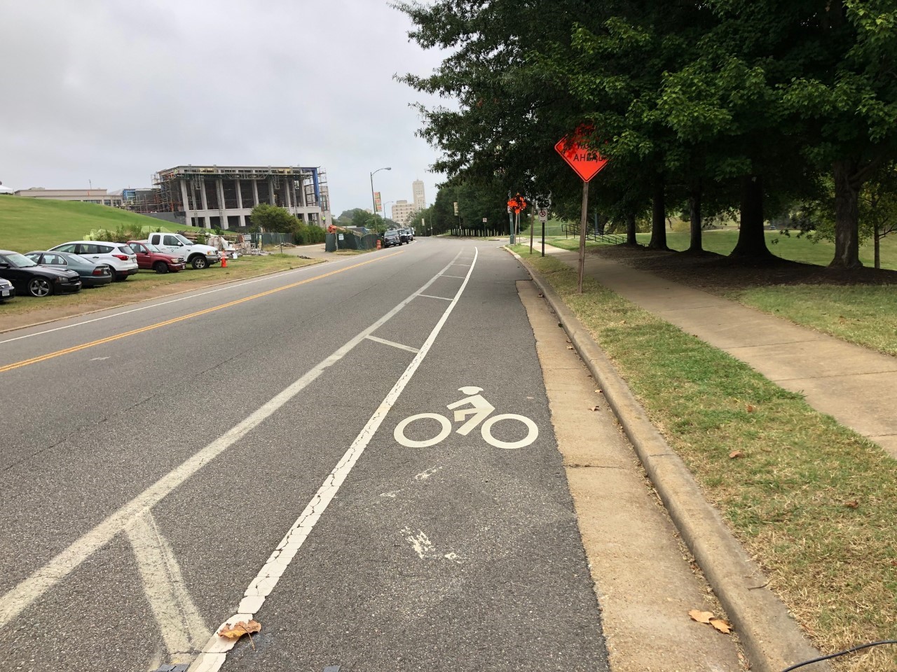
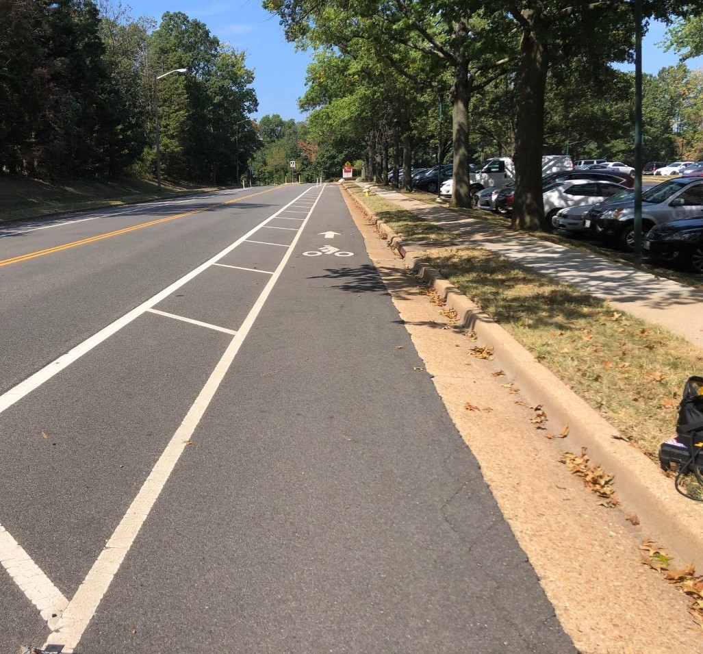
- Buffered bicycle lanes are one-way facilities running along the curb, shoulder, or on-street parking lane that carry bicycle traffic in the same direction as motor vehicle traffic.
- A buffered bicycle lane is similar to a traditional bicycle lane, but with additional separation from the adjacent travel or parking lane by a buffer space.
- A buffered bicycle lane is designated by pavement markings and signing for the preferential use of bicycles. The buffer space is typically designated by additional parallel, diagonal, or chevron striping, but does not include vertical separation.
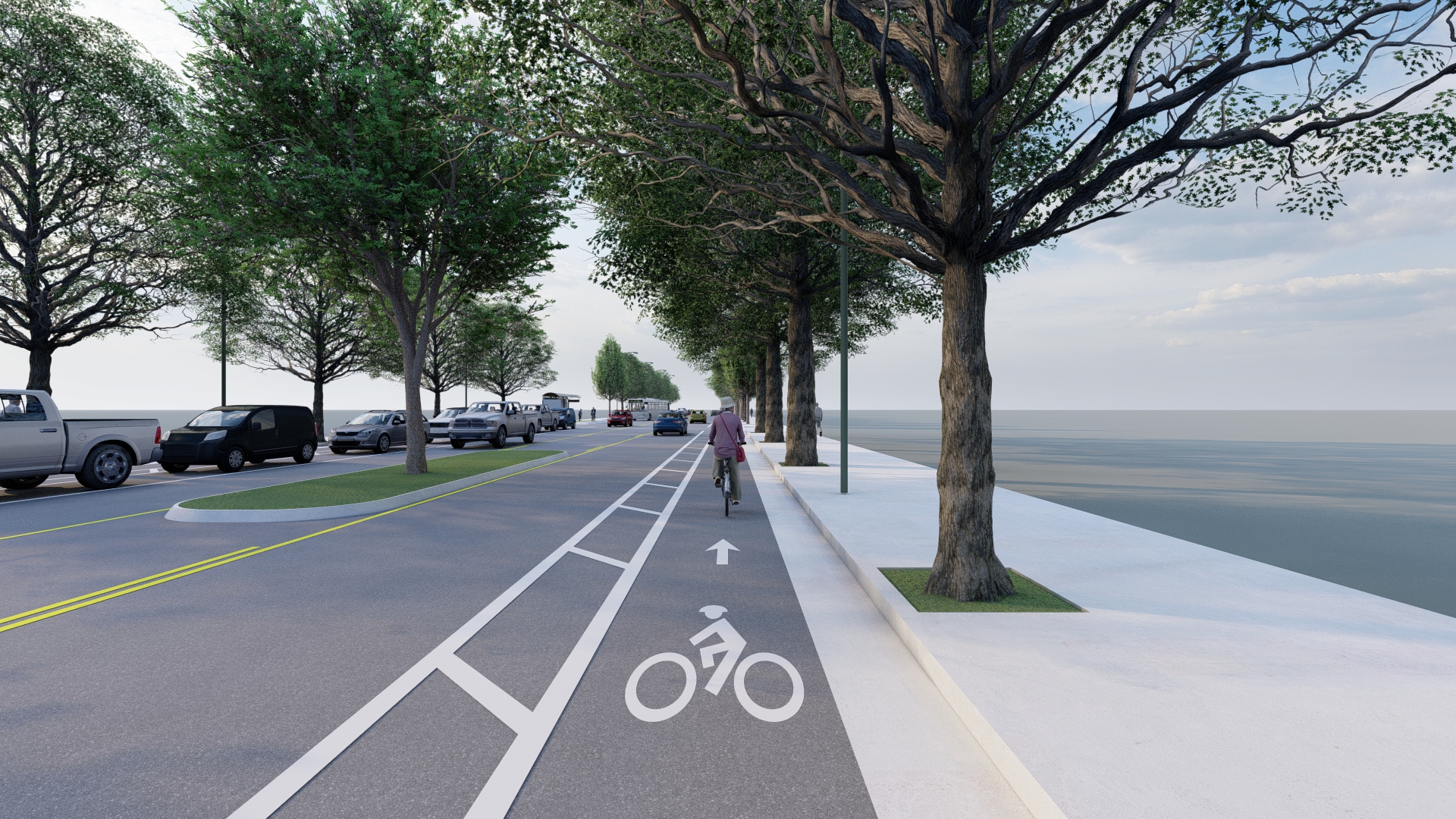
A buffered bicycle lane running alongside the curb (for illustrative purposes only)
How To Use a Buffered Bicycle Lane
- Bicyclists may use a buffered bicycle lane just as they would a traditional bicycle lane. As they ride, bicyclists should be aware of turning motor vehicles and opening doors. A bicyclist may leave a buffered bicycle lane to pass other users, make turns, or avoid obstacles.
- Drivers may cross through a buffered bicycle lane only to make a right turn or to enter/exit a parking spot. When making a right turn or accessing parking, drivers are required to yield to bike traffic, then merge into the bike lane and turn from the curb or park. In these instances, the bicyclist should pass on the left as the driver merges to the right.
- Drivers may not drive or park in a buffered bicycle lane unless weather conditions, an accident, or another emergency situation requires them to do so.
Context
- A buffered bicycle lane is appropriate anywhere a traditional bicycle lane is installed or considered (on streets with moderate average daily traffic, speeds above 25 mph, and with high transit vehicle volumes)
- A buffered bicycle lane is particularly appropriate on streets with higher speeds, volumes, or truck traffic, where greater physical separation for bicyclists can increase levels of comfort and safety for both bicyclists and motorists as compared to traditional bicycle lanes.
- On streets without parking, a buffered bike lane is recommended when average daily traffic (ADT) exceeds 6,000 and design or posted speeds are between 30-35 mph.
- On streets with parking, a buffered bike lane is recommended when ADT is between 3,000-6,000 and design or posted speeds are between 25-35 mph.
- A buffered bicycle lane is often considered on streets with extra lanes or width.
Benefits
- Improved safety: provides separation from motor vehicles, establishes predictable riding behavior, visually reminds motorists of bicyclists’ presence and right of way, provides greater shy distance between motor vehicles and bicyclists, protects bicyclists from opening doors
- Improved comfort: allows bicyclists to travel at their preferred speed, provides ample space for passing other bicyclists, appeals to wide range of bicycle users
- Traffic compliance: reduces wrong way riding, prevents road users from mistaking wide bicycle lane as travel or parking lane
- Increased efficiency: increases capacity of the roadway
Policy and Design Guidance
Guidelines are provided for informational purposes only. For detailed design guidance, please refer directly to the design manuals and standards listed below in Resources.
- Wider bicycle lanes provide higher levels of capacity and comfort and they facilitate safer passing and side-by-side riding without needing to leave the bicycle lane.
- Care should be taken to assure the width of the “rideable surface” is adequate; the measured width of the lane should take into account possible obstacles such as gutters, as well as clearance from vertical elements such as curbs or guardrails.
- Generally, buffered bicycle lanes are positioned on the right side of the street, unless vehicle travel is one-way, in which case the bike lane may be positioned on either side.
- Bike lanes should have a smooth riding surface and be free of raised utility covers and debris.
- A double solid white line is often used to demarcate the lane. If wide enough, the buffer should include interior diagonal cross hatching or chevron markings. In some cases, the buffer area may use different paving materials, such as bricks or textured materials, to provide horizontal separation.
- At intersections, buffered bicycle lanes should be transitioned to the left of a right turn only lane or a combined bike lane/turn lane should be used. Buffer markings should transition to a single dashed line.
- Green pavement markings paint may be used to increase visibility of the bicycle lane.
- Bicycle lane pavement markings should be periodically stenciled in the bicycle lane, especially following intersections.
- Buffered bicycle lanes typically cost $85,000 - $320,000 per mile. (Low end of cost estimates assumes only thermoplastic lane lines and signage. High end of cost estimates assumes all above and continuous application of green pavement markings in conflict areas.)
Examples of Buffered Bicycle Lanes
 A buffered bicycle lane on Seminary Road in Alexandria, VA (Kittelson & Associates, Inc.)
As part of a Complete Streets project, buffered bicycle lanes were installed on Seminary Road in Alexandria, VA to provide the most protection possible on this heavily trafficked corridor. At key locations, green paint was used to supplement signage and other pavement markings.
 A buffered bicycle lane on Twin Hickory Road in Henrico County, VA
Henrico County installed buffered bike lanes on Twin Hickory Road to provide a designated place for people to ride bicycles to schools and businesses, and to extend the reach of their existing bicycle facility network.
 A buffered bicycle lane on Singletons Way in Centreville, VA
As part of a repaving project, buffered bicycle lanes were installed on Singletons Way in Centreville, VA. By narrowing wide travel lanes to make room for the bike lanes, existing on-street parking was maintained on both sides of the road.
 Buffered bicycle lanes provide a dedicated space for bicyclists to ride on 2nd Street in Richmond, VA
The 2nd Street buffered bicycle lanes are only a small part of Richmond, VA’s growing bicycle network.
 These buffered bicycle lanes on North Van Dorn Street in Alexandria, were installed as part of a wider Complete Streets initiative
One year after buffered bicycle lanes were installed on North Van Dorn Street in Alexandria, VA, flex posts were added in the buffer space to upgrade the facilities to separated bicycle lanes.
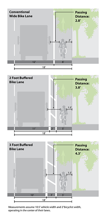
A comparison of passing distances between traditional and buffered bicycle lanes (Urban Bikeway Design Guide, NATCO)
Buffered bicycle lanes provide greater shy distance between vehicles and bicyclists than traditional bicycle lanes, often with minor changes to the roadway cross section.
Resources
Legal definitions and regulations:
Treatment applications and general design guidance:
- NACTO, Urban Bikeway Design Guide, Buffered Bike Lanes
- AASHTO, Guide for the Development of Bicycle Facilities
Geometric design guidance for Virginia:
Pavement markings, signage, and spacing:
- MUTCD 2009 Edition Part 3, Chapter 3D, Figure 3D-2. Markings for Buffer-Separated Preferential Lanes
- MUTCD 2009 Edition Part 9, Chapter 9C, Figure 9C-3. Word, Symbol, and Arrow Pavement Markings for Bicycle Lanes
- MUTCD 2009 Edition Part 3, Chapter 3B, Section 3B.24. Chevron and Diagonal Crosshatch Markings
- MUTCD 2009 Edition Part 9, Chapter 9B, Signs
- VDOT 2016 Road and Bridge Standards, Volume II, Section 1330.60
Rural applications:
Description
Resource Links
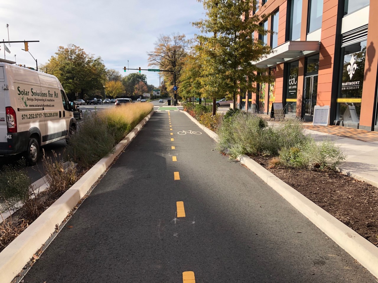
- A separated bicycle lane, also known as a cycle track or protected bicycle lane, provides both horizontal and vertical separation between bicyclists and adjacent vehicles, offering the comfort and safety of a shared use path with the proximity of the road right of way.
- Separated bicycle lanes run along the curb or shoulder. On streets with on-street parking, they are located to the curb-side of parking.
- Separated bicycle lanes may be one-way or two-way. While other bike lanes are at street level, separated bicycle lanes may be at grade with the sidewalk or at an intermediate level between the sidewalk and street.
- Horizontal separation may be provided by striping or different paving materials, similar to a buffered bicycle lane. Vertical separation may be provided by flex posts, a parking lane, a median, a landscaped buffer, or by raising the lane to an intermediate or sidewalk level.

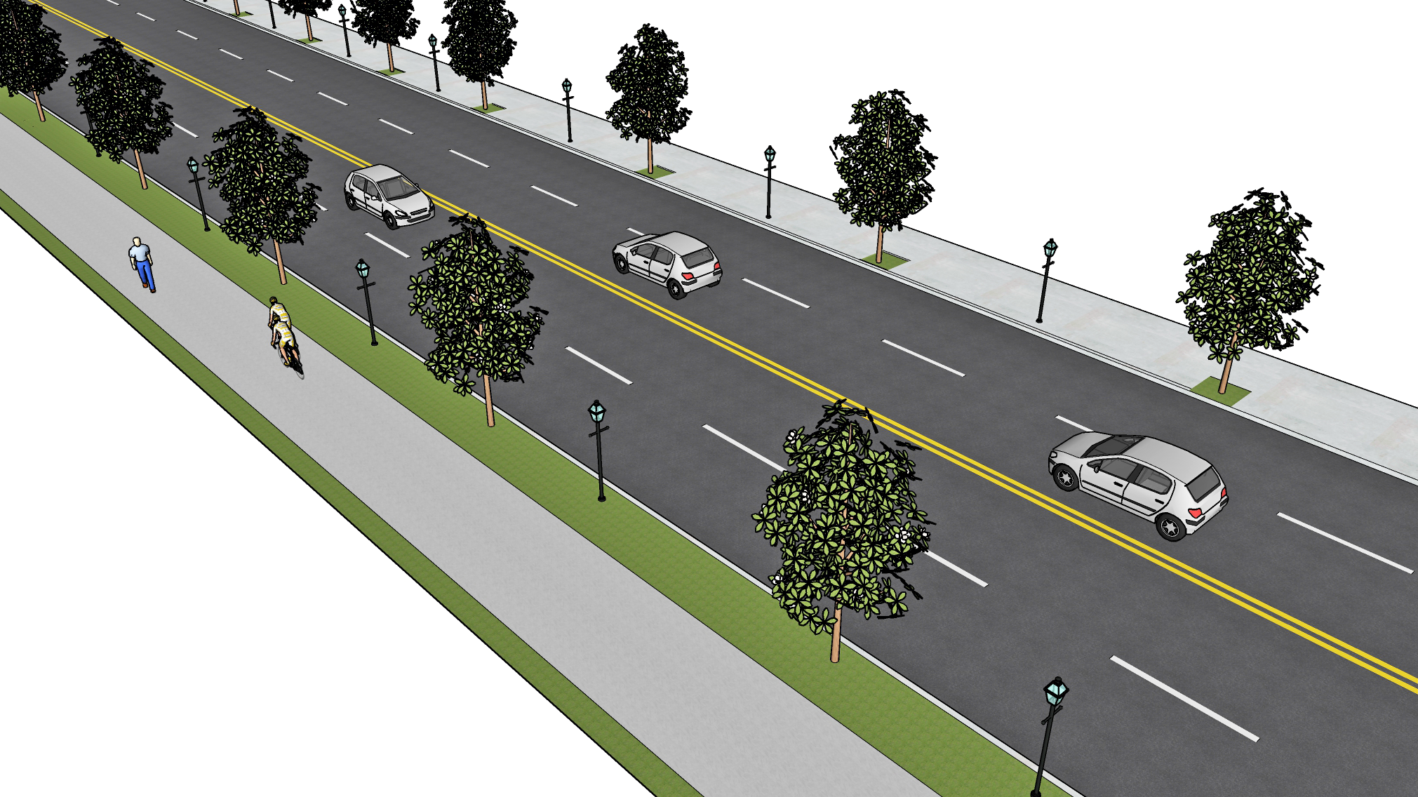
A two-way separated bicycle lane separated by a landscaped median and on-street parking (for illustrative purposes only)
How To Use a Separated Bicycle Lane
- Much like on a traditional or buffered bicycle lane, bicyclists may leave a separated bicycle lane to make turns or avoid obstacles. If the lane is located adjacent to on-street parking, bicyclists should be aware of opening doors.
- At intersections or driveways, motorists should yield to bicyclists biking through before turning with caution.
- At transit stops, bicyclists should yield to people getting on or off transit vehicles and wait for the lane to clear before proceeding.
Context
- A separated bicycle lane is often installed on streets with high-stress features such as multiple lanes, high traffic volumes and speeds, and high demand for parking.
- A separated bicycle lane is particularly appropriate on streets with existing high bicycle volumes or on streets whose features prevent people from biking comfortably even with a traditional or buffered bike lane.
- A separated bicycle lane is often considered on streets with extra lanes or width.
- Two-way separated bicycle lanes are appropriate on streets with few access points, where contraflow bicycle travel is needed, where there is not enough room for separated facilities on both sides, or where destinations are concentrated on one side of the street.
Benefits
- Improved safety: provides separation from motor vehicles, establishes predictable riding behavior, visually reminds motorists of bicyclists' presence and right of way, provides greater shy distance between motor vehicles and bicyclists, protects bicyclists from opening doors, reduces conflicts with pedestrians that can occur on side paths or shared use paths.
- Improved comfort: allows bicyclists to travel at their preferred speed, provides ample space for passing other bicyclists, appeals to wide range of bicycle users.
- Traffic compliance: reduces wrong way riding, prevents road users from mistaking wide bicycle lane as travel or parking lane.
- Increased efficiency: increases capacity of the roadway.
- Safer speeds: vertical separation doubles as traffic calming and can help to reduce driver speeds.
Policy and Design Guidance
Guidelines are provided for informational purposes only. For detailed design guidance, please refer directly to the design manuals and standards listed below in Resources.
- Wider bicycle lanes provide higher levels of capacity and comfort and they facilitate safer passing and side-by-side riding without needing to leave the bicycle lane. Separated bicycle lanes, in particular, require sufficient shy distance between bicyclists and vertical separation.
- Care should be taken to assure the width of the "rideable surface" is adequate; the measured width of the lane should take into account possible obstacles such as gutters, as well as clearance from vertical elements such as curbs or guardrails.
- If one-way, separated bicycle lanes are typically positioned on the right side of the street. However, on one-way streets or in two-way applications, the lane may be positioned differently.
- Bike lanes should have a smooth riding surface and be free of raised utility covers and debris.
- A solid double white line is often used to demarcate the lane. If wide enough, the buffer should include interior diagonal cross hatching or chevron markings. In some cases, the buffer area may use different paving materials, such as bricks or textured materials, to provide horizontal separation.
- Vertical separation may be provided by flex posts, a parking lane, a median, planters, or a landscaped buffer. The separation type may be based on the presence of on-street parking, lane widths, cost, aesthetics, emergency vehicle access, and maintenance.
- At intersections and transit stops, a combination of design treatments and specialized signalization can help to protect bicyclists as they proceed through these conflict points.
- Green pavement markings may be used to increase visibility of the bicycle lane.
- Bicycle lane pavement markings should be periodically stenciled in the bicycle lane, especially following intersections.
- Two-way facilities require special attention at intersections or other conflict points and include additional pavement markings such as dashed centerlines or directional arrows.
- Raised lanes may have a mountable curb to allow entry and exit for passing bicyclists or turning vehicles.
- Separated bicycle lanes typically cost $215,000 - $760,000 per mile. (Low end of cost estimates assumes parking-separate lanes and high end assumes median separation.)
Examples of Separated Bicycle Lanes
 A two-way separated bicycle lane on Fairfax Drive on Arlington, VA
Fairfax Drive in Arlington features a two-way separated bicycle lane. Separation between the travel lanes and the bicycle lane is provided by a landscaped median.
 A one-way separated bicycle lane on Llewellyn Avenue in Norfolk, VA
The City of Norfolk installed separated bicycle lanes on Llewellyn Avenue as part of the Pilot Bike Loop Project. After the installation, more bicyclists began to use the street and driver speeds were reduced.
 A one-way separated bicycle lane on Mosby Street in Richmond, VA
The Mosby Street Bike and Pedestrian Safety Improvement Project included new crosswalks, pavement markings, signage, and separated bicycle lanes as part of a broader road diet. These facilities provided important safety benefits to students at a nearby school and to residents of a nearby apartment complex.
 Potential Intersection Crossing Treatments for Separated Bike Lanes (Small Town and Rural Design Guide, FHWA)
A variety of treatments can be used to safely transition separated bicycle facilities through intersections. In all cases, parking should be prohibited within 20 feet of the intersection to improve visibility for turning vehicles and people biking through the intersection.
Resources
Legal definitions and regulations:
- Code of Virginia, § 46.2-100. Definitions
- Code of Virginia, § 46.2-907. Overtaking and passing vehicles
- Code of Virginia, § 46.2-841. When overtaking vehicle may pass on right.
- Code of Virginia, § 46.2-905. Riding bicycles, electric personal assistive mobility devices, electric power-assisted bicycles, motorized skateboards or scooters, and mopeds on roadways and bicycle paths.
Treatment applications and general design guidance:
- NACTO, Cycle Tracks
- AASHTO, Guide for the Development of Bicycle Facilities
- FHWA, Separated Bike Lane Planning and Design Guide
Geometric design guidance for Virginia:
Pavement markings, signage, and spacing:
- MUTCD 2009 Edition Part 3, Chapter 3D, Figure 3D-2. Markings for Buffer-Separated Preferential Lanes
- MUTCD 2009 Edition Part 9, Chapter 9C, Figure 9C-3. Word, Symbol, and Arrow Pavement Markings for Bicycle Lanes
- MUTCD 2009 Edition Part 3, Chapter 3B, Section 3B.24. Chevron and Diagonal Crosshatch Markings
- MUTCD 2009 Edition Part 9, Chapter 9B, Signs
- VDOT 2016 Road and Bridge Standards, Volume II, Section 1330.60
- Virginia Supplement to the MUTCD, Chapter 9
Rural applications:
Description
Resource Links
- A contraflow bicycle lane provides bicyclists a dedicated space in which to ride in the opposite direction of motor vehicle traffic on a one-way street.
- Contraflow lanes may include horizontal or vertical separation, like buffered or separated bicycle lanes, or they may resemble traditional bicycle lanes with simple pavement markings and signing. Parallel yellow stripes are typically used to designate the lane.

A contraflow bicycle lane runs against vehicle traffic (for illustrative purposes only)
How To Use a Contraflow Bicycle Lane
- Bicyclists should use a contraflow bicycle lane the same way they would use a traditional, buffered, or separated bicycle lane, the only difference being that they will be traveling against motor vehicle traffic.
- As they ride, bicyclists should be aware of turning motor vehicles. A bicyclist may leave a contraflow bicycle lane to pass other users, make turns, or avoid obstacles, but they should be keenly aware of oncoming motor vehicle traffic.
- At intersections, bicyclists should be aware of turning vehicles and drivers should turn with caution, watching for people riding bikes in the opposite direction.
- Drivers may not drive or park in a contraflow bicycle lane unless weather conditions, an accident, or another emergency situation requires them to do so.
Context
- Contraflow bicycle lanes are most appropriate on low speed, low volume one-way streets unless further horizontal or vertical separation can be provided.
- A contraflow bicycle lane is often installed on streets with large numbers of bicyclists riding the wrong way or where the bicycle network could benefit from safer or more direct routes.
- Contraflow bicycle lanes are most successful on streets with few intersecting access points and where bicyclists can safely transition to other infrastructure at the end of the contraflow lane.
Benefits
- Improved safety: provides separation from motor vehicles, establishes predictable riding behavior, visually reminds motorists of bicyclists' presence and right of way.
- Improved comfort: allows bicyclists to travel at their preferred speed, provides ample space for passing other bicyclists, appeals to wide range of bicycle users.
- Traffic compliance: reduces wrong way riding and sidewalk riding.
- Increased efficiency: decreases trip distance and travel time for bicyclists.
- Safer speeds: doubles as traffic calming and can help to reduce driver speeds.
Policy and Design Guidance
Guidelines are provided for informational purposes only. For detailed design guidance, please refer directly to the design manuals and standards listed below in Resources.
- Wider bicycle lanes provide higher levels of capacity and comfort and they facilitate safer passing and side-by-side riding without needing to leave the bicycle lane.
- Care should be taken to assure the width of the "rideable surface" is adequate; the measured width of the lane should take into account possible obstacles such as gutters, as well as clearance from vertical elements such as curbs or guardrails.
- Contraflow bicycle lanes should be positioned on the right side of the road (from the perspective of the bicyclist).
- A contraflow lane may be positioned between a parking lane and the curb; however, this configuration may reduce sight lines so contraflow bicycle lanes are better suited on streets without on-street parking on the lane side.
- When parking is not present, a solid double yellow line is often used to demarcate the lane to demonstrate opposite directions of travel. If wide enough, the buffer should include interior diagonal cross hatching or chevron markings. In some cases, the buffer area may include vertical separation elements, such as medians or flex posts.
- Bike lanes should have a smooth riding surface and be free of raised utility covers and debris.
- Lane markings should be dashed through intersections or other merging areas to alert drivers of the presence of the lane.
- "ONE WAY" or "DO NOT ENTER" signs should be supplemented with plaques reading "EXCEPT BIKES" to alert both drivers and bicyclists of the presence of opposing traffic.
- Green pavement markings may be used to increase visibility of the bicycle lane.
- Bicycle lane pavement markings should be periodically stenciled in the bicycle lane, especially following intersections.
- Contraflow bicycle lanes typically cost $85,000 - $320,000 per mile. (Low end of cost estimates assumes only thermoplastic lane lines and signage. High end of cost estimates assumes all above and continuous application of green pavement markings in conflict areas.)
Examples of Contraflow Bicycle Lanes
 A contraflow bicycle lane on 9th Street S in Arlington,VA
As part of the Columbia Pike Bike Boulevards project, Arlington installed a contraflow bicycle lane on 9th Street S, providing bicyclists with a safer and more direct route to common destinations in the area.
 A contraflow bicycle lane on Llewellyn Avenue in Norfolk, VA (Google Earth)
A contraflow lane on Llewellyn Avenue in Norfolk helps to provide two-way bicycle travel along the extent of an important north/south corridor.
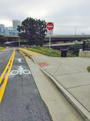 A contraflow bicycle lane on Oregon Hill Parkway in Richmond, VA (Bike Walk RVA)
Richmond's first contraflow bicycle lane on the Oregon Hill Parkway increased access to the Belvidere Bridge and downtown.
Resources
Legal definitions and regulations:
- Code of Virginia, § 46.2-100. Definitions
- Code of Virginia, § 46.2-907. Overtaking and passing vehicles
- Code of Virginia, § 46.2-841. When overtaking vehicle may pass on right.
- Code of Virginia, § 46.2-905. Riding bicycles, electric personal assistive mobility devices, electric power-assisted bicycles, motorized skateboards or scooters, and mopeds on roadways and bicycle paths.
Treatment applications and general design guidance:
Geometric design guidance for Virginia:
Pavement markings, signage, and spacing:
- MUTCD 2009 Edition Part 3, Chapter 3D, Figure 3D-2. Markings for Buffer-Separated Preferential Lanes
- MUTCD 2009 Edition Part 9, Chapter 9C, Figure 9C-3. Word, Symbol, and Arrow Pavement Markings for Bicycle Lanes
- MUTCD 2009 Edition Part 3, Chapter 3B, Section 3B.01. Yellow Center Line Pavement Markings and Warrants
- MUTCD 2009 Edition Part 3, Chapter 3B, Section 3B.24. Chevron and Diagonal Crosshatch Markings
Bicycle Treatments at Intersections
Description
Resource Links
- The use of green colored pavement markings within bicycle lanes and bicycle queuing areas can help increase the visibility of bike facilities and remind motorists to watch for bicyclists.
- Green pavement markings increase comfort levels for bicyclists and can be used in conjunction with any type of bicycle lane (traditional, buffered, separated, or contraflow).
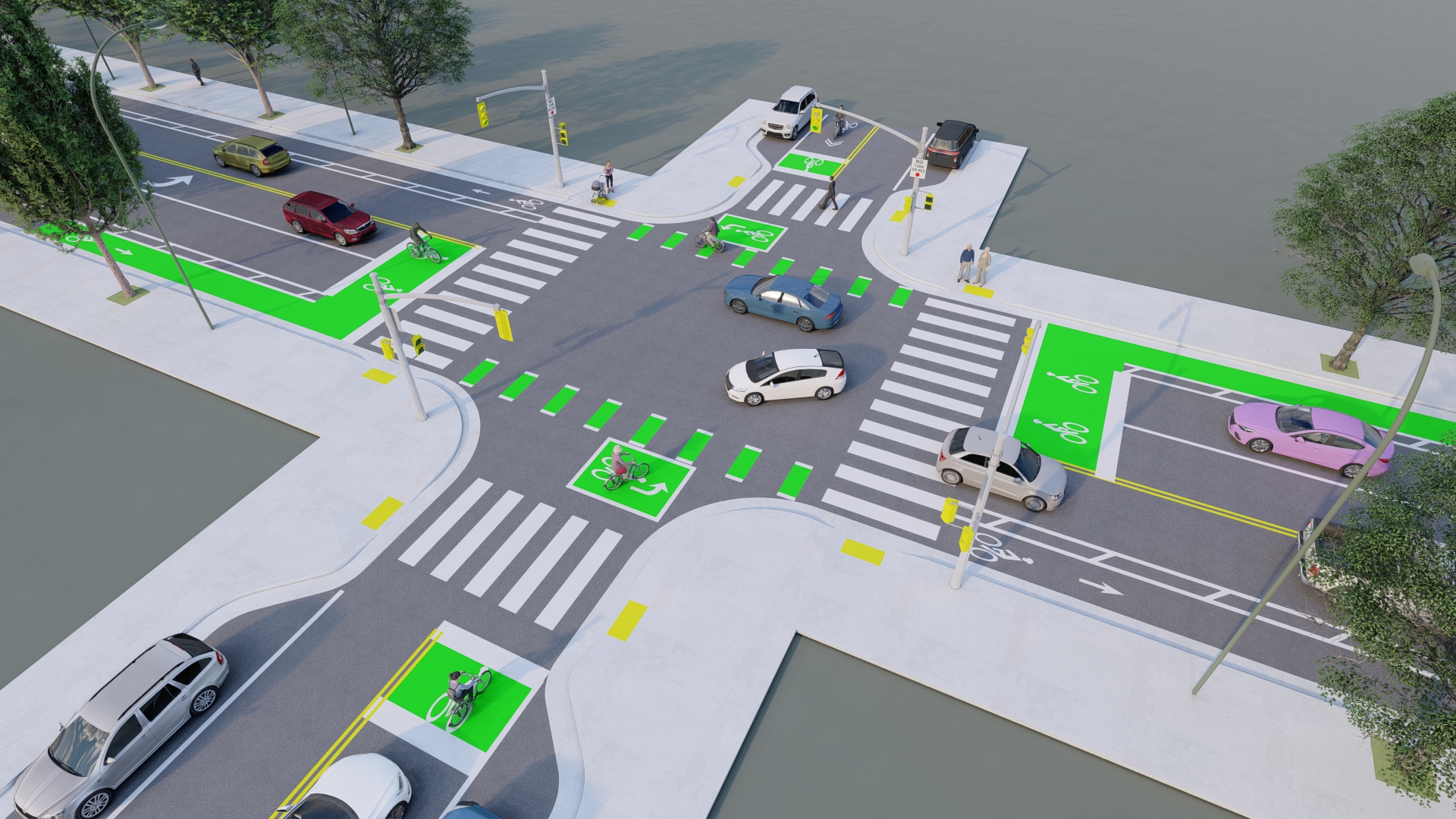
Green pavement markings can be used to mark where bicycle lanes traverse intersections (for illustrative purposes only)
How To Use Green Pavement Markings
- Green pavement markings are provided chiefly to increase the visibility of bicycle facilities. They do not change the operations or restrictions of bicycle lanes.
- Dashed pavement markings are typically used in merging areas such as across intersections or driveways. When traversing these lanes, motorists should proceed with caution and watch for bicyclists traveling through.
Context
- Green pavement markings can be applied along the entirety of a bicycle facility or used as a spot treatment.
- Typically, green pavement markings are used to highlight bicycle lanes as they traverse intersections or driveways, in bike boxes and two-stage left-turn boxes, or in other conflict areas.
Benefits
- Improved safety: Visually reminds motorists of bicyclists' presence and right of way.
- Improved comfort: Increases visibility of bicycle lane, thereby enhancing dedicated space for bicyclists.
- Traffic compliance: Reduces illegal parking in the bike lane.
Policy and Design Guidance
Guidelines are provided for informational purposes only. For detailed design guidance, please refer directly to design manuals and standards listed below in Resources.
- When green pavement markings are used, they should be installed in a consistent manner along a corridor to provide clear guidance for all roadway users.
- Green pavement markings supplement, but do not replace the white pavement markings that legally establish the bicycle facility.
- Green pavement markings may be installed in a dashed pattern through intersections and across merging areas. In these locations, dashed white bike lane lines shall be provided along the edge of the colored lane.
- Green pavement markings shall be retroreflective and should use a skid-resistant material.
- Green pavement markings may be installed as an overlay, using paint, thermoplastic, or other pavement marking materials, or they may be embedded as colored asphalt. Overlay materials are recommended for pilot installations or spot treatments, while embedded treatments are better for corridor treatments.
- The maintenance of green pavement markings is important to ensure the effectiveness of the application.
- Green pavement markings for bike lanes are not currently included in the 2009 MUTCD and may be installed in Virginia per FHWA’s Interim Approval. Localities may install green pavement markings without seeking separate Interim Approval, however each road agency is responsible for ensuring they comply with FHWA’s Interim Approval requirements.
- Pavement marking materials range from $2 - $20 per square foot, depending on material and expected performance. Bicycle lanes may range from $85,000 - $320,000 per mile (Low end of cost estimates assumes only thermoplastic lane lines and signage. High end of cost estimates assumes all above and continuous application of green pavement markings in conflict areas.)
- Periodic maintenance of pavement markings will require an additional cost.
Examples Of Green Pavement Markings
 A green bicycle lane and bike box at the intersection of Rugby Road and University Avenue in Charlottesville, VA
 Green paint is used periodically along the buffered bicycle lanes on Seminary Road in Alexandria, VA (Kittelson & Associates, Inc.)
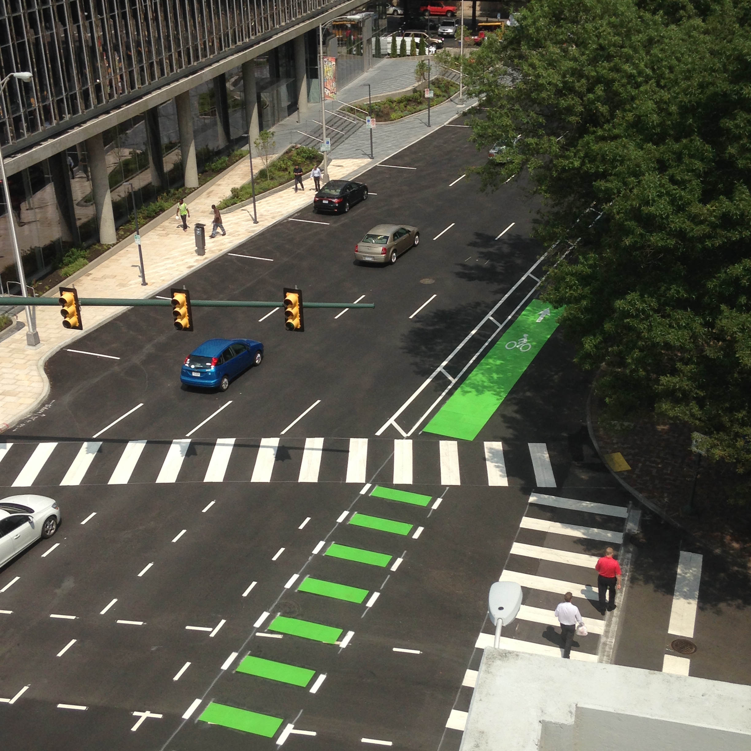 Green paint is used with buffered bicycle lanes on S 9th Street in Richmond to highlight
the bike lane as it continues across the intersection (City of Richmond)
Resources
Treatment applications and general design guidance:
- NACTO, Colored Bike Facilities
- NACTO, Colored Pavement Material Guidance
- AASHTO, Guide for the Development of Bicycle Facilities
- FHWA, Separated Bike Lane Planning and Design Guide
Geometric design guidance for Virginia:
Pavement markings, signage, and spacing:
- MUTCD Part 9 Section 3G. Colored Pavements
- MUTCD Interim Approval IA-14 - VDOT has received IA from FHWA
- VDOT Road and Bridge Standards, Volume II, Section 1330.60
- Virginia Supplement to the MUTCD, Chapter 9
Material Guidance
Description
Resource Links
- When designed appropriately, roundabouts can be an important part of a comfortable and connected bicycle network. Urban roundabouts, in particular, are designed to control vehicle speeds such that the difference in speed between bicyclists and motorists are minimized.
- Depending on the location, roundabouts can be designed to direct bicyclists to travel through in the center of the travel lane, on the sidewalk, or on a separated facility or shared use path. Bicycle lanes without vertical separation are not to be provided on the circular roadway of a roundabout.
- When planning bicycle facilities at roundabouts it is important to provide appropriate space for bicyclists, minimize conflict points between people walking, biking, and driving, maximize visibility, and minimize stop-start maneuvers for all users.
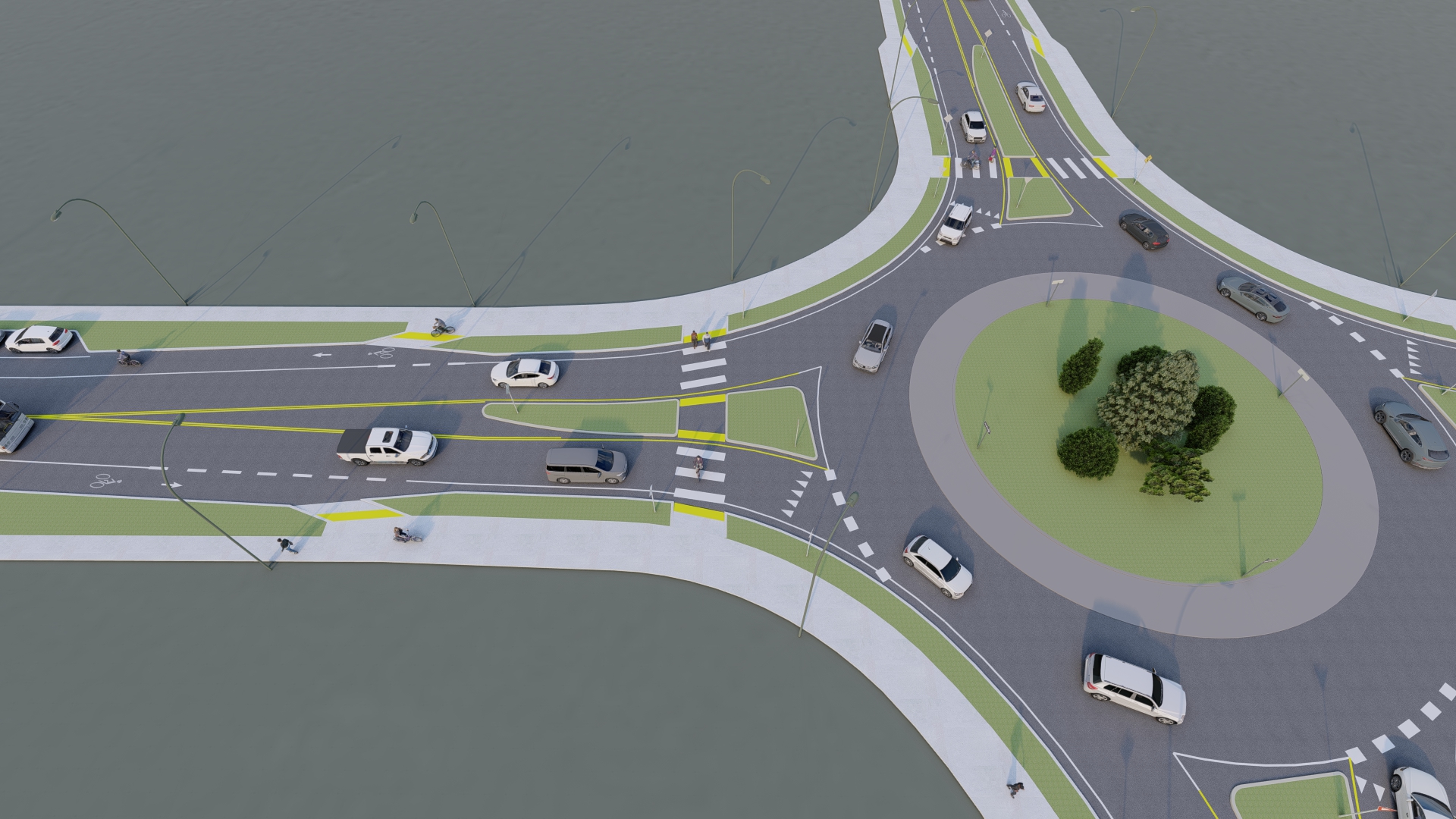
One of the ways bicyclists can be accommodated at roundabouts is by directing them onto shared use paths ahead of the intersection (for illustrative purposes only)
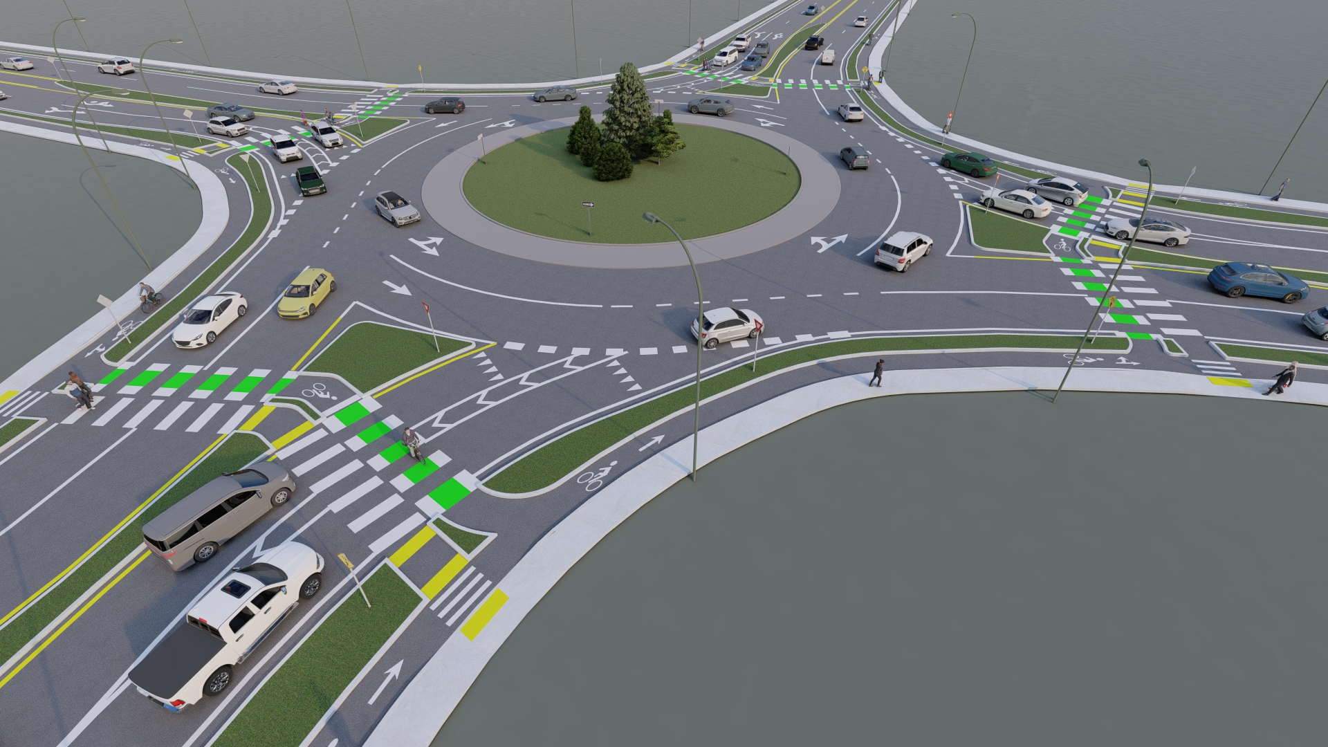
Bicyclists can also be accommodated with separated bicycle facilities at roundabouts (for illustrative purposes only)
How to Navigate a Roundabout by Bicycle
- Bicyclists may choose to travel through a roundabout in the travel lane with vehicle traffic. When doing so, bicyclists should yield to vehicles already in the roundabout and clearly signal when they intend to exit the roundabout.
- Where a separated facility or shared use path exists, bicyclists may ride through the roundabout on those facilities.
- Alternatively, bicyclists may choose to move to the sidewalk and travel through a roundabout as a pedestrian. When doing so, bicyclists should dismount and walk their bicycle as they proceed through the intersection.
- Motorists should yield to all bicycle and pedestrian traffic at roundabouts and be prepared to stop at crosswalks and crossbikes on roundabout approaches.
Context
- At most urban, single-lane roundabouts, on-street bicycle lanes should be terminated in advance of the intersection, directing bicyclists onto a separated bike lane or shared use path via a ramp. If a separated bike lane or shared use path is not provided, bicyclists should be directed to merge into traffic for circulation with other vehicles and encouraged to ride in the center of the lane.
- At multilane roundabouts, complex single-lane roundabouts, or locations with existing bicycle facilities, directing bicyclists to merge into traffic is not preferred. Bicycle ramps should be provided to allow bicyclists to exit the roadway onto a separated bicycle lane or shared use path which will follow the contour of the intersection and provide crossings adjacent to pedestrian crossings at each intersection leg.
- In constrained locations, bicyclists can be guided onto the sidewalk to proceed through the intersection as a pedestrian.
Benefits
- Improved safety: Reduces conflict points and severity, reduces crossing distances for both bicyclists and pedestrians.
- Shorter wait times: Decreases wait times for bicyclists and pedestrians wishing to cross.
- Safer speeds: Reduces the speed differential between bicyclists and motorists, reduces vehicle speeds.
Policy and Design Guidance
Guidelines are provided for informational purposes only. For detailed design guidance, please refer directly to design manuals and standards listed below in Resources.
- It is possible to install different bicycle treatments at different intersection legs depending on the bicycle facilities present on each approach.
- When terminating a bicycle lane approaching a roundabout, an appropriate taper should be provided to narrow the lane widths and encourage bicyclists to merge. Bicycle facility striping should be dashed approaching the taper.
- At roundabout exits, an appropriate taper should begin after the crosswalk and the bicycle facility should resume as soon as the appropriate width is available.
- At roundabouts where bicycle ramps are provided, a widened sidewalk or shared use path should be considered, depending on expected bicycle volumes.
- Bicycle ramps must be designed to ensure usability by bicyclists and to avoid the potential for confusion of pedestrians, especially those with visual impairments, who will be focusing on determining appropriate crossing locations and when to initiate crossing. Crossing treatments, including standard pedestrian signals, pedestrian hybrid beacons (PHB), rectangular rapid flashing beacons (RRFB), and raised crosswalks can limit the risk experienced by these pedestrians.
- Roundabouts vary in cost depending on the roadway context, size, and right-of-way acquisitions. For example, a temporary mini-roundabout costs approximately $50,000 and a standalone multilane roundabout can cost up to $4M. Separated bicycle lanes typically cost $215,000 - $760,000 per mile, paved shared use paths average $250,000 per mile, and curb ramps typically cost between $1,000-$5,000.
Examples of Bicycle Facilities at Roundabouts
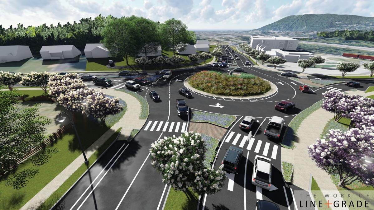 Roundabout design with bicycle ramps in Roanoke, VA (Line and Grade Civil Engineers)
In Roanoke, VA, near the Virginia Western Community College campus, recent roadway changes included the installation of three roundabouts on Colonial Avenue. When the project is complete, bicycle ramps will direct bicyclists from buffered bicycle lanes onto wide sidewalks through the roundabouts.
 This temporary roundabout installation in Fairfax County included separated bicycle facilities
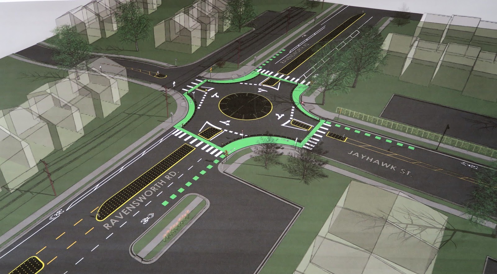 Although bicyclists may choose to ride through this roundabout in the travel lanes, they are encouraged to use the separated bicycle lanes and crossings (The Annandale Blog)
In 2018, a temporary modular mini roundabout was installed at the intersection of Ravensworth Road and Jayhawk Street in Annandale. At the roundabout, existing bicycle lanes on the intersection approaches were guided to separated bike lanes between approaches and shared pedestrian crossings.
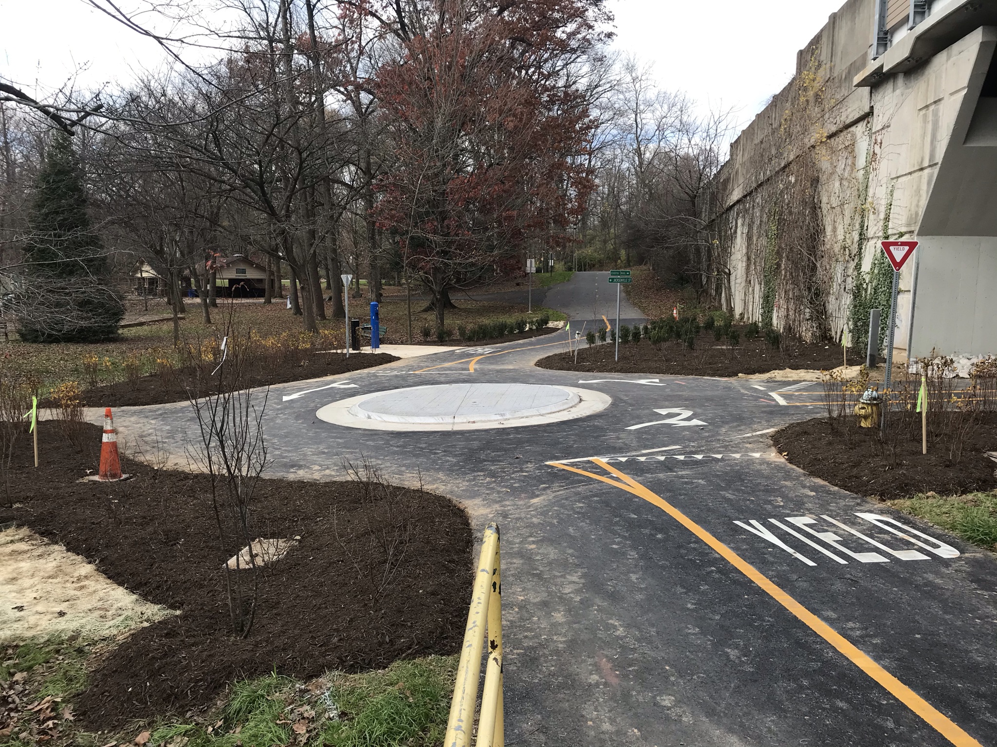 A trail roundabout improves sightlines for pedestrians and bicyclists traveling on the Custis Trail
Small traffic circles operating similarly to roundabouts can also be designed for the exclusive use of non-motorists. Recently, a trail roundabout was installed on the Custis Trail near Arlington 's Bon Air Park. This roundabout improved safety conditions for trail users by improving sightlines at this intersection near an underpass.
Resources
Legal definitions and regulations:
Bikes at roundabouts design guidance:
- NCHRP Report 672, Section 6.8.2
- AASHTO, Guide for the Development of Bicycle Facilities, Section 4.12.11
General roundabout design guidance:
Geometric design guidance for Virginia:
Pavement markings, signage, and spacing:
Description
Resource Links
- A bike box is a designated area placed ahead of a travel lane at a signalized intersection in which bicyclists can safely get ahead of stopped traffic during a red light.
- Bike boxes help to prevent conflicts between bicyclists and right-turning vehicles and increase the visibility of bicyclists at intersections by facilitating better left-turn positioning and giving bicyclists a head start when the signal changes.
- A two-stage left-turn box is a marked area in an intersection in which bicyclists can safely wait and prepare to make a two-stage left-turn.
- Two-stage left-turn boxes can also help facilitate transitions from cycle tracks or shared use paths and prevent the need for cyclists to merge into traffic or across several travel lanes to make a left turn.
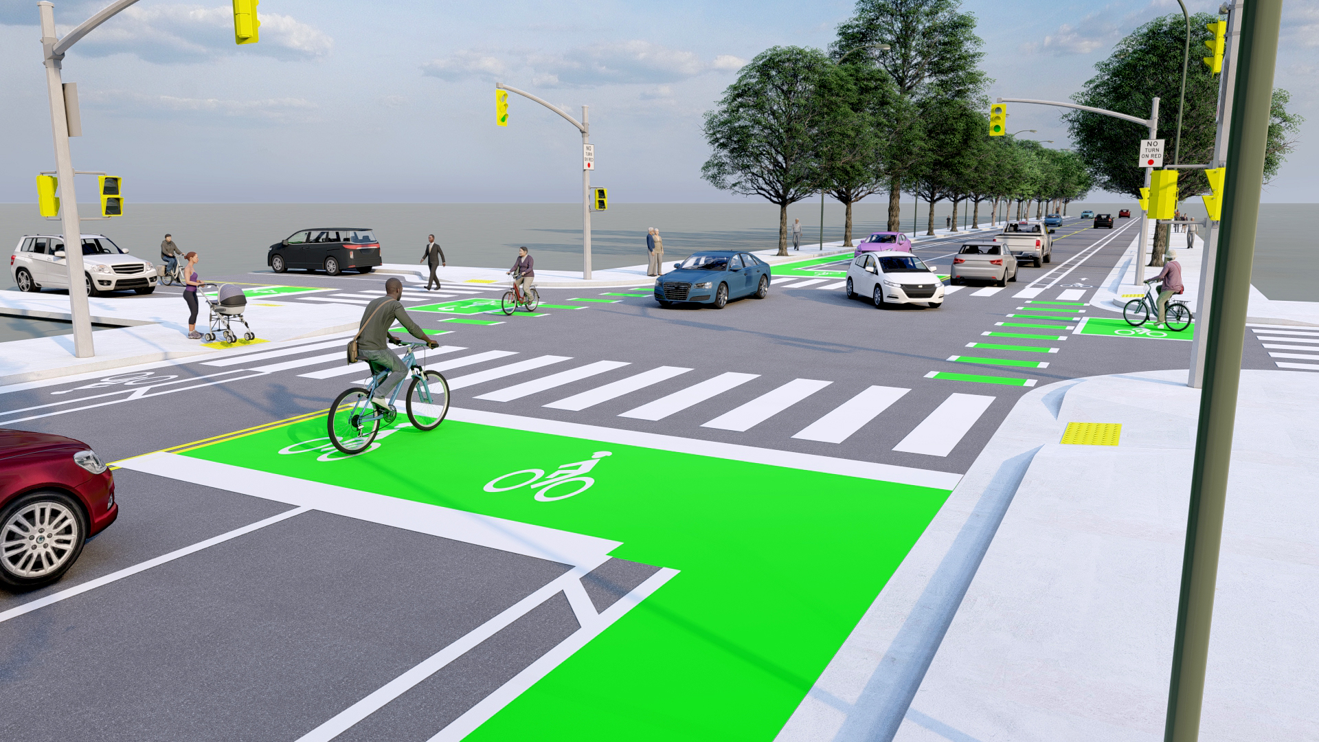
A bike box provides a designated area for bicyclists to stop at a red light (for illustrative purposes only)
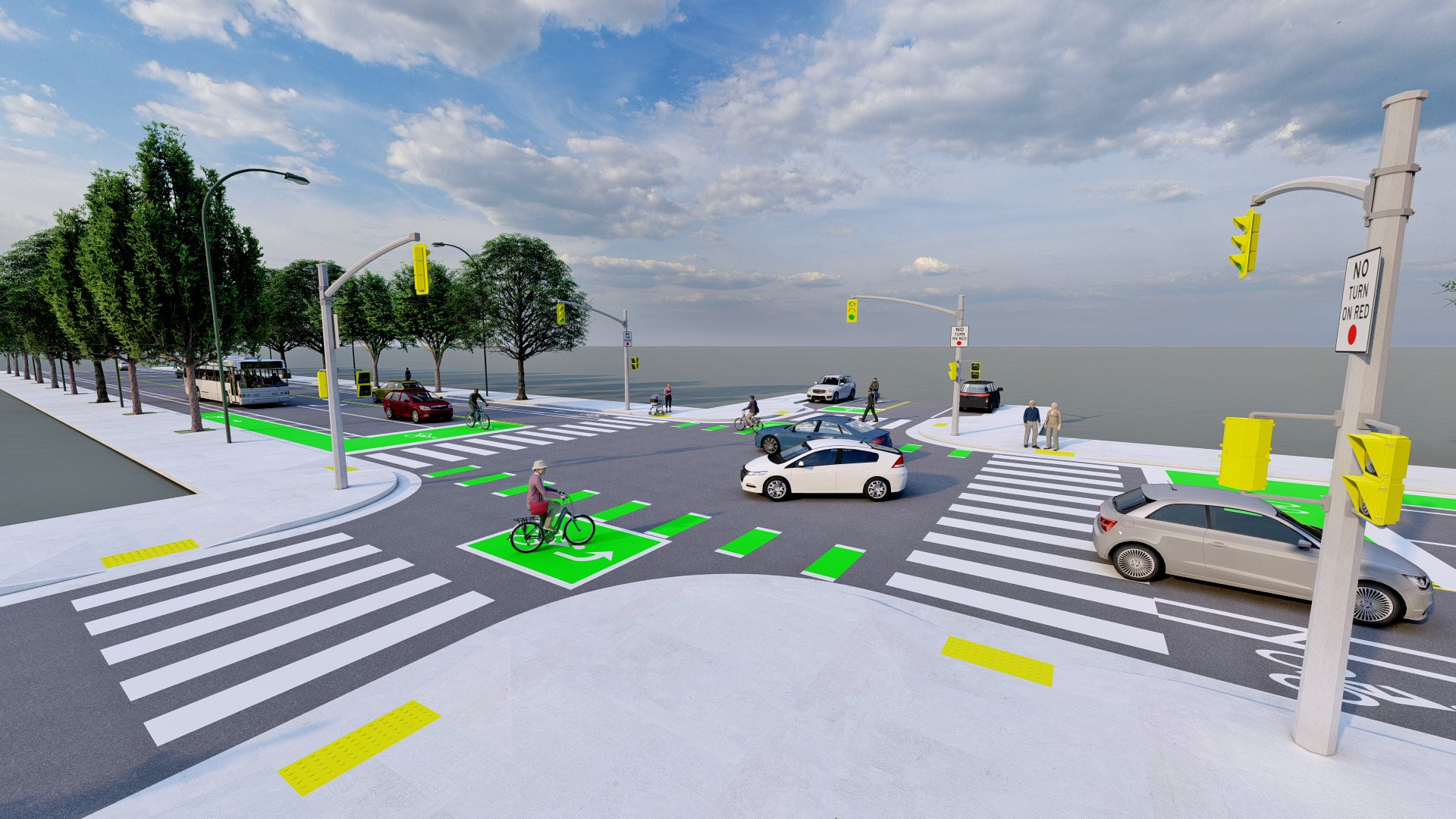
A two-stage left-turn box provides a space where bicyclists can safely wait while they make a two-stage left-turn (for illustrative purposes only)
How To Use Bike Boxes & Two-Stage Left-Turn Boxes
- A bicyclist approaching a bike box on a red light should proceed to the bike box, move in front of vehicles, and wait for a green light. Left-turning bicyclists should move to the left side of the bike box, positioning themselves to turn ahead of vehicles when the signal changes.
- Bicyclists make a two-stage left-turn by first proceeding through the intersection to the two-stage turn box. Here, they wait for the signal to change before proceeding across the rest of the intersection.
- During a red light, motorists shall not enter the bike box or two-stage left-turn box.
Context
- Bike boxes are typically installed at signalized intersections with high volumes of both vehicles and bicycles.
- Bike boxes are particularly appropriate at locations with frequent bicyclist left-turns, motorist right-turns, or where a bicycle lane transitions to the left side of the street.
- Two-stage left-turn boxes are typically installed at signalized intersections where at least one intersecting road has more than one lane.
- Two-stage left-turn boxes may also be installed along cycle tracks, at midblock crossings, or at intersections with streetcar tracks to facilitate safer crossing angles.
Benefits
- Improved safety: increases visibility of bicyclists at intersections; reduces turning conflicts between bicyclists and motorists; bike boxes reduce encroachment of vehicles on crosswalks
- Increased efficiency: separates turning bicyclists from through bicyclists; bike boxes reduce signal delay for bicyclists and groups bicyclists together to clear an intersection quickly
- Improved comfort: bike boxes allow bicyclists to get ahead of vehicles at intersections; two-stage left-turn boxes remove the need for left-turning bicyclists to merge into traffic
Policy and Design Guidance
Guidelines are provided for informational purposes only. For detailed design guidance, please refer directly to design manuals and standards listed below in Resources .
- Bike boxes are formed by two stop lines, one near the crosswalk and an advanced stop line at least 10 feet upstream, indicating the point behind which motorists are required to stop.
- An ingress bicycle lane should be used to define the bicycle space entering the bike box, and an egress bicycle lane may be used to clearly define the bicycle space through the intersection.
- Bike boxes may extend across multiple travel lanes or just the rightmost lane. Where the box is provided across multiple lanes, countdown pedestrian signals shall be provided for the crosswalk across the approach on which the bicycle box is located to inform cyclists of the remaining red signal phase time.
- At least one bicycle symbol shall be placed within the bike box.
- Two-stage left-turn boxes shall be placed in an area outside the travel paths of conflicting vehicles (for example, in the buffer space created by a separated bike lane, parking lane, or crosswalk setback).
- A bicycle stencil and turn arrow shall be included in a two-stage left-turn box to indicate proper bicycle direction and positioning.
- Passive detection must be provided at two-stage left-turn boxes if signals are not timed.
- Bike boxes or two-stage left-turn boxes may be combined with bike signals that allow bicyclists to clear the intersection or reach the queue box before motorists are allowed to proceed.
- At intersections with either bike boxes or two-stage left-turn boxes, right-turns on red shall be prohibited to prevent motorists from entering the bike boxes.
- Green pavement markings are often used as a background color for both bike boxes and two-stage left-turn boxes to increase visibility and compliance.
- Bike boxes and two-stage left-turn boxes are not currently included in the 2009 MUTCD. Localities wishing to install these treatments must seek Interim Approval through the FHWA.
- Pavement marking materials range from $2 - $20 per square foot, depending on material and expected performance. Bicycle lanes leading to boxes may range from $85,000 - $320,000 per mile (Low end of cost estimates assumes only thermoplastic lane lines and signage. High end of cost estimates assumes all above and continuous application of green pavement markings in conflict areas.)
- Periodic maintenance of pavement markings will require an additional cost.
Examples of Bike Boxes & Two-Stage Left-Turn Boxes
A bike box at the intersection of Rugby Road and University Avenue in Charlottesville
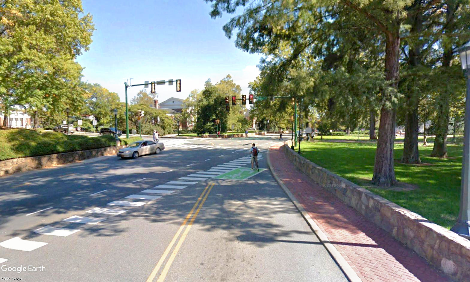 A bicyclist waits at a two-stage left-turn box in Charlottesville (Effectiveness of Innovative Pavement Markings in Facilitating Safer Bicycle Travel, Peter Ohlms & Young-Jun Kweon)
Resources
Treatment applications and general design guidance:
- NACTO, Urban Bikeway Design Guide, Bike Boxes
- NACTO, Urban Bikeway Design Guide, Two-Stage Turn Queue Boxes
- AASHTO, Guide for the Development of Bicycle Facilities
- Virginia Transportation Research Council
Geometric design guidance for Virginia :
Pavement markings, signage, and spacing:
- MUTCD 2009 Edition Part 9 Figure 9C-3. Word, Symbol, and Arrow Pavement Markings for Bicycle Lanes
- MUTCD Interim Approval IA-18 - Requires IA from FHWA
- MUTCD Interim Approval IA-20 - Requires IA from FHWA
- VDOT 2016 Road and Bridge Standards, Volume II, Section 1330.60
- Virginia Supplement to the MUTCD, Chapter 9
Material Guidance
Description
Resource Links
- Protected intersections, also known as offset or setback intersections, refer to a collection of intersection treatments that are designed to maintain the separation provided by bicycle lanes through the intersection. In this way, they can improve bicyclists' visibility to turning motorists and minimize the potential for conflict between modes.
- The main features of protected intersections include setbacks, corner islands, queuing areas, pedestrian islands and waiting zones. These design features help to physically separate pedestrians and bicyclists from vehicles driving through or making turns.
- Elements of protected intersections may be installed individually, but they are most effective when installed together.
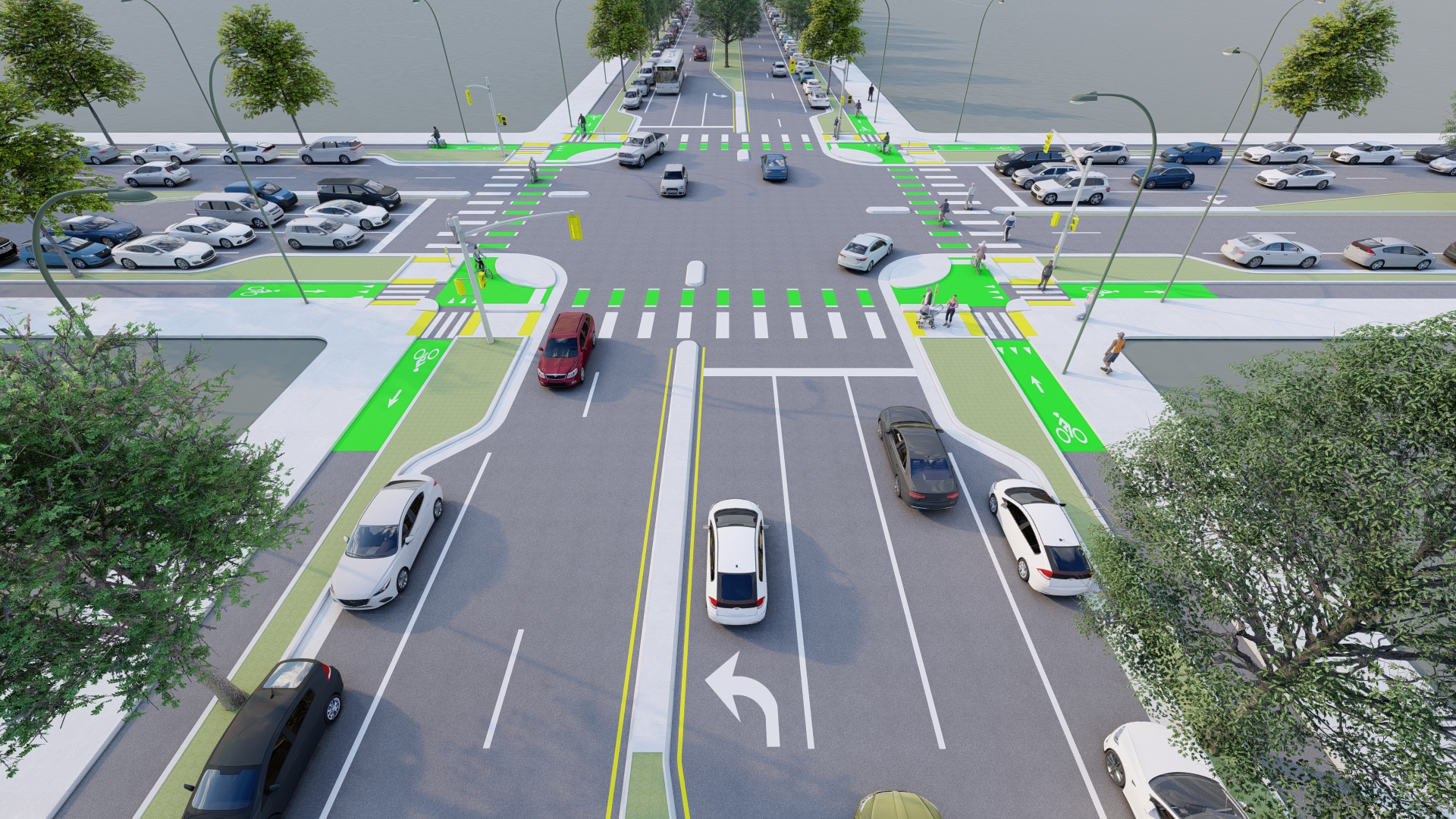
A protected intersection maintains the separation provided by bicycle lanes through the intersection (for illustrative purposes only)
How To Use a Protected Intersection
- At a protected intersection, bicyclists making a right turn or traveling through should simply follow the bicycle lane.
- Bicyclists turning left should make a two-stage left-turn by first proceeding through the intersection to the far-side curb, where they can wait behind the corner island for the signal to change, and then proceed across the other leg of the intersection.
- Bicyclists should yield to pedestrians at crosswalks.
- Pedestrians crossing at protected intersections should cross as they normally would. The pedestrian pushbutton will often be found on the pedestrian island.
- Motorists traveling through protected intersections should stop at stop bars and turn carefully as they normally would.
- Right- and left-turning motorists must yield to bicyclists traveling through and crossing pedestrians. Right-turning motorists are able to yield in the motorist waiting zone, out of the path of through-moving vehicles.
Context
- Protected intersections are commonly installed on streets where enhanced bicycle infrastructure is desirable or there are high volumes of bicyclists.
- Typically, candidate locations already have buffered or separated bicycle lanes on at least one street.
- Due to the specific design features of protected intersections, constrained or skewed geometry can make installation difficult. However, design variations that preserve the main features of protected intersections are possible.
- Protected intersections may be installed on a temporary or pilot basis using interim materials.
Benefits
- Improved safety: reduces crossing distances for both bicyclists and pedestrians, reduces speeds of turning vehicles, setback provides bicyclists with a head start on the green signal.
- Improved comfort: maintains separation for bicyclists through the intersection.
- Traffic compliance: reduces encroachment of vehicles into the bicycle lane.
- Increased efficiency: design better supports high volumes of bicycles and pedestrians, increasing the capacity of the intersection.
Policy and Design Guidance
Guidelines are provided for informational purposes only. For detailed design guidance, please refer directly to design manuals and standards listed below in Resources.
- The main features of a protected intersection include:
- No Stopping/No Standing zone, where parking is prohibited near the intersection
- Pedestrian islands, where pedestrians can request the pedestrian signal and wait safely between the bicycle lane and the vehicle travel lane
- Bike queue area, where bicyclists can wait for the green signal ahead of the crosswalk
- Bikeway setback, which increases visibility and reaction time for bicyclists to notice turning vehicles
- Corner islands, which protect the bike queue areas, slow turning traffic, and provide physical separation between bicyclists and turning vehicles
- Motorist waiting zone, where right-turning motorists can safely wait and yield to through-moving bicyclists before completing a turn
- Intersection crossing markings, which delineate where the bicycle lane continues through the intersection
- Bike yield line, ahead of where the bicycle lane intersects with the crosswalk (optional)
 The main features of a protected intersection design (for illustrative purposes only)
- In conjunction with physical design features, protected intersections often also include bicycle signals or bicycle-friendly signal phasing.
- Portions of corner islands can be painted or made mountable at intersections with considerable turning heavy vehicle traffic.
- The cost of a protected intersection depends on the intersection context and which design elements already exist.
- Separated bicycle lanes typically cost $215,000 - $760,000 per mile
- Curb ramps typically cost between $1,000 - $5,000
- Corner islands and crossing islands range from $2,140 - $41,170 depending on design and site conditions
- High-visibility crosswalks typically cost $8 per linear foot
- Bicycle lanes typically cost $85,000 - $320,000 per mile (Low end of cost estimates assumes only thermoplastic lane lines and signage. High end of cost estimates assumes all above and continuous application of green pavement markings in conflict areas.)
Examples of Protected Intersections
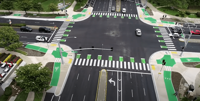 This protected intersection design on Walnut Avenue protects bicyclists as they wait for the green light, as they make turns, and as they cross through the intersection (Streetsblog)
The city of Fremont, CA has installed several protected intersections along the Walnut Avenue Bikeway to improve safety for bicyclists and pedestrians and to provide safe routes for bicyclists of all ages and abilities.
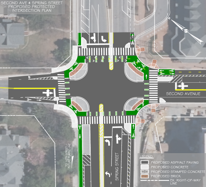 This protected intersection design integrates several other bicycle and pedestrian treatments, including green pavement markings, high visibility crosswalks, and left-turn hardening (MCDOT)
 Mountable corner islands allow large vehicles to make turns at protected intersections
The Montgomery County Department of Transportation Engineering installed a protected intersection in Silver Spring, MD as one component in a network of improvements including separated bicycle lanes and "floating" bus stops. This design featured mountable corner islands to accommodate turning heavy vehicles.
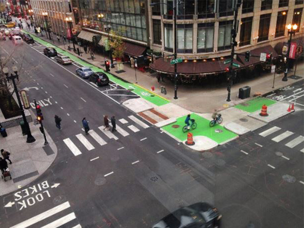 This protected intersection is designed around a two-way separated bicycle lane (Streetsblog)
The Chicago Department of Transportation included protected intersections as an important element of larger transit improvements. As part of the Loop Link bus rapid transit project, four protected intersections were installed to better protect bicyclists from turning vehicles. These locations are unique in that they accommodate a two-way cycle track.
Resources
Treatment applications and general design guidance:
- NACTO, Don't Give Up at the Intersection
- PEDSAFE
- Protected Intersections for Bicyclists
- FHWA, Separated Bike Lane Planning and Design Guide
Geometric design guidance for Virginia:
Pavement markings, signage, and spacing:
